background image


11

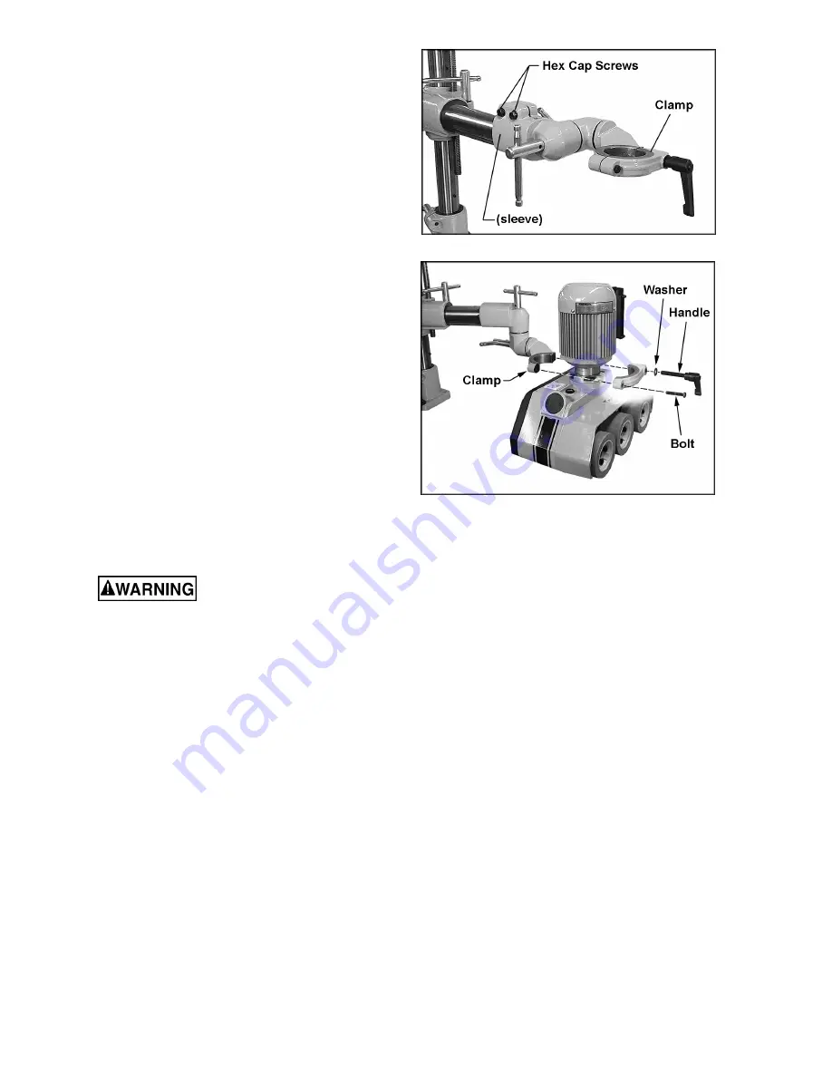
17.  Mounting  the  feeder  body  may  be  easier  if 

you  loosen the two hex cap screws (shown 
in  Figure  8)  and  rotate  the  over  arm  cone 
assembly  so  that  the  clamp  is  toward  the 
bottom,  as  shown  in  Figure  9.  Loosen  the 
handles  and rotate the cones as needed  to 
get  the  clamp  in  position.  Re-tighten  the 
screws  and  handles  before  mounting  the 
feeder body. 

18.  Unscrew the bolt and the  handle (Figure 9) 

from the clamp, and remove the outer half of 
the clamp.  

19.  Position the neck of the stock feeder into the 

inner half of the clamp, then attach the outer 
half  of  the  clamp.  Re-install  the  bolt  and 
handle  and  tighten  both  of  them  gradually 
and  in  turns,  until  the  clamp  is  evenly  tight 
over  the  stock  feeder  neck.  NOTE:  The 
seam  between  the  two  halves  of  the  clamp 
will not close entirely. 

The  handle  (Figure  9)  is  adjustable.  To 
tighten  it,  rotate  the  handle  clockwise,  then 
lift 

out 

on 

the 

handle, 

rotate 

it 

counterclockwise  on  the  pin  and  release  it, 
making  sure  it  re-seats  itself  on  the  pin. 
Continue  this  procedure  until  tight.  (This 
adjustable  feature  allows  the  handle  to  be 
re-positioned  at  any  time  while  remaining 
tight.) 

Grounding Instructions 


Electrical  connections  must 

be  made  by  a  qualified  electrician  in 
compliance  with  all  relevant  codes.  This 
machine must be properly grounded to help 
prevent  electrical  shock  and  possible  fatal 
injury.


The PF-series Feeders are available in voltages 
ranging  from  115  to  460,  depending  on  the 
model you purchased. Make sure the voltage of 
your power supply matches the specifications on 
the motor plate of the stock feeder. 

The  Stock  Feeder  is  not  supplied  with  an 
electrical  plug.  You  may  either  connect  an 
appropriate  UL/CSA  listed  plug,  or  “hard-wire” 
the machine directly to a service panel.  

If the stock feeder is to be hard-wired to a panel, 
make  sure  a  disconnect  is  available  for  the 
operator.  Also  make  sure  the  fuses  have  been 
removed  or  the  breakers  have  been  tripped  in 
the  circuit  to  which  the  stock  feeder  will  be 
connected. Place a warning placard on the fuse 
holder  or  circuit  breaker  to  prevent  it  being 
turned on while the machine is being wired.  


Figure 8 


Figure 9 


The stock feeder must comply with all local and 
national codes after being wired.  

This machine must be grounded. In the event of 
a malfunction or breakdown, grounding provides 
a path of least resistance for electric current,  to 
reduce the risk of electric shock to the operator. 
Improper connection of the equipment-grounding 
conductor  can  result  in  a  risk  of  electric  shock. 
The  conductor,  with  insulation  having  an  outer 
surface  that  is  green  with  or  without  yellow 
stripes, is the equipment-grounding conductor.  If 
repair or replacement of the electric cord or plug 
is  necessary,  do  not  connect  the  equipment-
grounding conductor to a live terminal. 


Summary of Contents for PF Series

Page 1: ...and Parts Manual 4 Speed Stock Feeders Models PF 31 PF 33 PF 41 PF 43 Powermatic 427 New Sanford Road LaVergne Tennessee 37086 Part No M 1790800 Ph 800 274 6848 Revision D1 11 2018 www powermatic com Copyright 2014 Powermatic ...

Page 2: ... product requires further inspection the Technical Service representative will explain and assist with any additional action needed Powermatic has Authorized Service Centers located throughout the United States For the name of an Authorized Service Center in your area call 1 800 274 6846 or use the Service Center Locator on the Powermatic website More Information Powermatic is constantly adding ne...

Page 3: ...Position 12 Speed Selection 12 Operating Controls 13 Operation 13 General Operating Instructions 14 When Used with a Shaper 14 When Used with a Table Saw 15 When Used with a Jointer 15 Roller Removal Replacement 16 Lubrication 17 Replacement Parts 18 PF 31 33 Feeder Body 19 Parts List PF 31 33 Feeder Body 20 PF 41 43 Feeder Body 22 Parts List PF 41 43 Feeder Body 23 Parts List Motor Assembly for P...

Page 4: ...f checking to see that keys and adjusting wrenches are removed from the machine before turning it on 14 Keep safety guards in place at all times when the machine is in use If removed for maintenance purposes use extreme caution and replace the guards immediately upon completion of maintenance 15 Make sure the stock feeder is firmly secured to an auxiliary machine before use 16 Check damaged parts ...

Page 5: ... that if precautions are not heeded it may result in serious injury or possibly even death SAVE THESE INSTRUCTIONS WARNING Drilling sawing sanding or machining wood products generates wood dust and other substances known to the State of California to cause cancer Avoid inhaling dust generated from wood products or use a dust mask or other safeguards for personal protection Wood products emit chemi...

Page 6: ...er in horizontal vertical or angled positions Specifications Model Number PF 31 PF 33 PF 41 PF 43 Stock Number 1Ph 115V 1790807K 1790812K Stock Number 3PH 230V 1790800K 1790811K Stock Number 3Ph 460V 1790810K na Height with handle in 29 1 2 29 1 2 Width in 18 23 1 2 Length with handle and arm fully extended in 43 1 4 43 1 4 Column Diameter in 2 1 4 2 1 4 Feed Rollers Dia x W in 4 3 4 x 2 3 8 Qty 3...

Page 7: ...7 Features and Terminology Figure 1 ...

Page 8: ...ead the instruction manual thoroughly for assembly maintenance and safety instructions Contents of the Shipping Container Carton 1 1 Stock Feeder 1 Grease Gun grease not included follow instructions on its packaging to fill 1 Boring Template 1 Owner s Manual not shown 1 Warranty Card not shown Carton 2 1 Feeder Mounting Assembly 1 Handle 1 Over Arm 1 Over Arm Cone Assembly 4 Hex Cap Screws M12x50 ...

Page 9: ...off loading stock and general maintenance The stock feeder and the auxiliary machine to which you are mounting it should both be disconnected from power during installation Refer to pages 14 through 16 for help in placing the stock feeder on a shaper table saw or jointer 1 Rest the feeder mounting assembly on the table of the auxiliary machine to determine the mounting location Figure 3 shows it b...

Page 10: ...sen the hex nut back off the socket head cap screw with a 5mm hex wrench as shown then re tighten the hex nut 11 Remove the screw from below the bracket then remove the handwheel Figure 6 12 Slide the end of the over arm that has the rack extending all the way to the edge into the bracket Figure 7 NOTE The rack will slide through the slot inside the bracket 13 Re install handwheel then reinstall s...

Page 11: ... help prevent electrical shock and possible fatal injury The PF series Feeders are available in voltages ranging from 115 to 460 depending on the model you purchased Make sure the voltage of your power supply matches the specifications on the motor plate of the stock feeder The Stock Feeder is not supplied with an electrical plug You may either connect an appropriate UL CSA listed plug or hard wir...

Page 12: ...osen handles F Tighten handles when adjustment is complete To rotate the stock feeder on its vertical axis loosen handle G just enough that the stock feeder will freely rotate Re tighten handle G before operating the stock feeder Edgewise Stock Feeder Position The stock feeder can be turned edgewise so that the feed is along the side of the workpiece This is useful when edging stock on a shaper or...

Page 13: ...witch for 3 phase units is shown in Figure 15 the control switches for 1 phase units are shown in Figure 16 Speeds are indicated by the universal symbols of hare high speed and tortoise low speed The switch can be turned for either forward or reverse direction If a jam should occur while feeding a workpiece DO NOT turn the stock feeder to reverse while the auxiliary machine is still running in for...

Page 14: ...e of varying thickness can be fed through the stock feeder without adjustments 6 When used in horizontal position the stock feeder should be adjusted for height so that the distance between the table and the feed rollers is approximately 1 8 3mm less than the thickness of the workpiece See Figure 17 7 Shaping hardwood with the stock feeder may increase the friction between workpiece and table Keep...

Page 15: ...n edgewise position keep in mind the spring tension of the rollers The distance between the shaper fence and the feed rollers should be approximately 1 8 3mm less than the thickness of the workpiece refer to Figure 17 When Used with a Table Saw 1 Position the 3 roller stock feeder so that the axis of the saw blade lines up between the center roller and outfeed roller See Figure 20 Position the 4 r...

Page 16: ...are four screws in each roller the two short screws unite the halves of the roller hub the two long screws secure the roller assembly to the feeder You only need to remove the two long screws to remove the roller assembly NOTE Replacement roller assemblies may have a one piece hub and thus the two short screws will no longer be needed See Figure 23 2 When a roller assembly is re mounted to the sto...

Page 17: ...ays dispose of used oil properly 3 Turn feeder body right side up and pour new oil into the fill hole until it is about 1 from the rim 4 Re install the oil cap Figure 25 Rollers NOTE Grease is not provided with the grease gun To fill the grease gun follow the instructions on its package Each of the rollers has a grease fitting located in the hub center as shown in Figure 26 Use the provided grease...

Page 18: ...pply Contact a qualified electrician Workpiece jams or moves sluggishly while passing beneath rollers Rollers too low Raise feeder Workpiece slips while passing under rollers Rollers too high no traction Lower feeder Grease or debris on rubber tires Clean tires Replacement Parts Replacement parts are listed on the following pages To order parts or reach our service department call 1 800 274 6848 M...

Page 19: ...19 PF 31 33 Feeder Body ...

Page 20: ...6 x 1 0P x 16 Lg 6 18 6288751A Sprocket Case PF 31 33 3 19 6289131 Lock Washer M12 3 21 6289126A Sprocket Shaft 1 24 6289228 Frame 4SP 1Ph 1 6289229 Frame 4SP 3Ph 1 25 6289139 Back Cover 1 26 6289136 Set Screw M6 x 1 0P x 10Lg 3 27 6288980 Oil Cap 1 28 6288979 O Ring 1 29 6288955 Snap Ring Ø26mm 3 30 6288954 Chain 40S 2 31 6288975 Chain 62S 1 32 6289092 Sprocket w Key 2 33 6288958 Snap Ring Ø15mm ...

Page 21: ...1 68 6289150 Star Washer 1 69 6288763 Cap Screw M5 x 0 8P x 12Lg 1 70 6289154 Cap Screw M5 x 0 8P x 10Lg 2 71 6289067 O Ring 1 72 6289148 Lock Pin Ø4 x 20mm 1 73 6289147 Gear Lever 1 74 6289152 O Ring 1 77 6288755 Snap Ring 20mm 3 78 6288756 Hex Screw M12 x 1 75P x 75Lg 3 79 6288757 Key 6 x 6 x 18 mm 1 80 6288758 Worm Gear Shaft 1 81 6288759 Snap Ring Ø22mm 1 82 6288760 O Ring 1 83 6288761 Cap 1 8...

Page 22: ...22 PF 41 43 Feeder Body ...

Page 23: ...Sprocket Case PF 31 33 41 43 4 19 6289131 Lock Washer M12 4 21 6289126A Sprocket Shaft 1 24 6289133 Frame 4SP 1Ph 1 6289134 Frame 4SP 3Ph 1 25 6289109 Back Cover 1 26 6289136 Set Screw M6 x 1 0P x 10Lg 4 27 6288980 Oil Cap 1 28 6288979 O Ring 1 29 6288955 Snap Ring Ø26mm 4 30 6288954 Chain 40S 2 31 6288975 Chain 62S 1 32 6289092 Sprocket w Key 2 33 6288958 Snap Ring Ø15mm 4 37 6289093 Sprocket w K...

Page 24: ... Star Washer 1 69 6288763 Cap Screw M5 x 0 8P x 12Lg 1 70 6289154 Cap Screw M5 x 0 8P x 10Lg 2 71 6289067 O Ring 1 72 6289148 Lock Pin Ø4 x 20mm 1 73 6289147 Gear Lever 1 74 6289152 O Ring 1 77 6288755 Snap Ring Ø20mm 4 78 6288756 Hex Screw M12 x 1 75P x 75Lg 4 79 6288757 Key 6 x 6 x 18 mm 1 80 6288758 Worm Gear Shaft 1 81 6288759 Snap Ring Ø22mm 1 82 6288760 O Ring 1 83 6288761 Cap 1 84 6288762 C...

Page 25: ...1 25P x 20Lg 4 4 6289085 Lock Washer 4 5 6289115 Control Switch 1 6 6289087 Capacitors set of 2 1 Start Capacitor 200MFD 125VAC 1 Run Capacitor 25 F 250VAC 1 THREE PHASE Index No Part No Description Size Qty 1 6289099 Motor 1HP 3Ph 460V 60Hz 1 6288988 Motor 1HP 3Ph 230V 60Hz 1 2 6289207 O Ring 1 3 6289086 Screw M8 x 1 25P x 20Lg 4 4 6289085 Lock Washer 4 5 6289003 Control Switch 1 ...

Page 26: ...26 Feeder Mounting Assembly for PF 31 33 and PF 41 43 ...

Page 27: ...16Lg 1 18 6289181 Over Arm Cone 1 19 6288930 Spring Washer M10 2 20 6289183 Bolt M10 x 1 5P x 50Lg 2 21 6289180 Elevating Bracket 1 22 6288912 Pinion M8 x 1 25P x 12Lg 3 23 6288913 Handwheel 1 24 6289166 Lock Pin 6 x 36 1 25 6288926 Handle Assembly 2 26 6288927 Lock Pin 6 x 22 2 27 6289176 Wheel Handle M10 x 1 5 1 28 6289221 Pin 6 x 36 1 29 6289175A Elevating Handle 1 30 6289222 Thrust Washer 1 31...

Page 28: ...Phase only GROUND 2 6 10 14 18 22 z 1 5 9 13 17 21 R S W X T 3 7 11 15 19 23 4 8 12 16 20 24 V U Y R S T Red 5 White 3 White 2 White 1 Red 4 Red 6 427 New Sanford Road LaVergne Tennessee 37086 Phone 800 274 6848 www powermatic com ...

Reviews: