background image


12

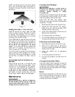
NOTE: The infrared sensor on the dust collector 
has a 120° line-of-sight angle. See Figure 12. 
Outside of this angle, the remote control may not 
be effective. 


Figure 12 

Setting the Timer 

(1-Phase Models)


While the machine is running, press the TIME 
button to activate the timer. Each time the button 
is pressed and released, the run time is 
incremented on the digital display by one minute 
and can be set up to 99 minutes. 

If the TIME button is pressed and held, the time 
will scroll up to 99 minutes, then start again at 
00. Release the button when the desired set 
time is reached. The dust collector will run for 
the amount of time displayed on the digital 
display. If you scroll past 99 and release the 
button at 10, for example, the machine will run 
for ten minutes, not 110 minutes. 

If the OFF button is pressed while machine is 
running with the timer engaged, the machine 
turns off and the timer is disengaged; i.e., when 
the machine is restarted, the timer must be 
reset. 

Connecting the Dust Collector to a 
Machine 

Use the proper type hose to connect the dust 
collector to the machine being operated.  

Dryer 

vent hose is not acceptable for this purpose.


Contact your nearest Powermatic distributor for 
a full line of Dust Collector hoses and 
accessories. You can customize your installation 
and obtain maximum performance with dust 
hoods, hoses, clamps, fittings, and blast gates. 

Maintenance 


Never perform maintenance 

on this machine before turning it OFF and 
removing plug from power source. Failure to 
comply may cause serious injury!


Cleaning the Filter Bags 


Wearing a particle mask or 

respirator for protection against fine dust 
particles during cleaning is highly 
recommended. 

During first use and after cleaning, the filter bags 
may allow some dust to escape. This is normal 
and will stop after a short period of time. 

Clean both the filter and collector bags 
frequently to keep the collector's performance at 
its optimum.  To clean: 

1.  Disconnect machine from the power source. 

2.  Unhook the filter bag from the hanger. 


Shake the bag so that the majority of the 
dust falls into the collector bag. 

3.  Loosen the retaining strap, and remove the 

filter bag from the housing. 

4.  Turn the bag inside-out and clean.   

5.  Turn the bag outside-in and re-attach to the 

housing using the retainer strap to secure.   

Removing the Collector Bags 

1.  Disconnect machine from the power source. 

2.  Remove the collector bag by pushing the 

ring of the collector bag upwards and pulling 
the bag out at an angle. 

3.  Empty the contents into an appropriate 

container. 

4.  Turn the bag inside-out and clean. 

5.  Turn the bag outside-in and insert into the 

housing.  

Cleaning the Canister Filters 

Clean the canister filters frequently to keep the 
collector's performance at its optimum. To clean 
the filter, turn the handle a couple of rotations so 
the dust falls into the clear plastic bag. Properly 
discard the plastic bag.  

Motor 

Make frequent inspections of the motor fan and 
blow out (with low pressure air hose) or vacuum 
any accumulation of foreign material in order to 
maintain normal motor ventilation.   


Summary of Contents for PM1900TX

Page 1: ...00TX with Filter Bag Kit 1792071K PM1900TX with Canister Kit 1792072K Powermatic 427 New Sanford Road LaVergne TN 37086 Part No M 1792071 Ph 800 274 6848 Revision B1 09 2018 www powermatic com Copyright 2014 Powermatic Now with This pdf document is bookmarked ...

Page 2: ...urning it on 14 Keep safety guards in place at all times when the machine is in use If removed for maintenance purposes use extreme caution and replace the guards immediately after maintenance is complete 15 Check damaged parts Before further use of the machine a guard or other part that is damaged should be carefully checked to determine that it will operate properly and perform its intended func...

Page 3: ...ne Serious injury could occur if the machine tips over Familiarize yourself with the following safety notices used in this manual This means that if precautions are not heeded it may result in minor injury and or possible machine damage This means that if precautions are not heeded it may result in serious injury or possibly even death SAVE THESE INSTRUCTIONS WARNING Drilling sawing sanding or mac...

Page 4: ...0 Electrical Connections 11 Extension Cords 11 Operating the Machine 11 Setting the Timer 1 Phase Models 12 Connecting the Dust Collector to a Machine 12 Maintenance 12 Cleaning the Filter Bags 12 Removing the Collector Bags 12 Cleaning the Canister Filters 12 Motor 12 Replacement Parts 13 Breakdown for PM1900TX Dust Collector Base Machine 13 Parts List for PM1900TX Dust Collector Base Machine 14 ...

Page 5: ...ine B with Canister Filter System 1792074K Filter Bag System only 1791075B Canister Filter System only 1791086 Blower Wheel Diameter 14 Sound Rating at 3 feet 86 92 db Inlet Port Diameter in three at 4 or one at 8 Air Flow at 8 Base Machine A and B CFM 1891 Velocity at 8 Base Machine A and B FPM 5393 7 Static Pressure inch of water 12 15 Bags and Canister Diameter in 20 Filter Bag Length in 48 Fil...

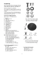
Page 6: ...ar 2 X Handle 2 Y Plate 2 Z Socket Head Cap Screw M8x12 4 Remote Control w batteries single phase machine only not shown Owner s Manual not shown Warranty Card not shown Main Hardware Bag contents Figure 1 A M8 x 20 Hex Cap Screws 34 B M6 x 12 Pan Head Flange Screws 8 C 3 16 x 1 2 Pan Head Flange Screw 1 D M8 Flat Washers 60 E M10 Flat Washers 6 F M8 Hex Nuts 30 G M8 Lock Washers 4 H 3 8 Hex Nuts ...

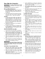
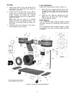
Page 7: ...flanges are aligned Note Refer to Figure 3 to make sure that the connector tube is facing the proper direction 3 Insert an M8x20 hex cap screw A through the M8 washer D and flanges of the connector tube R and impeller housing N 4 Place another washer D and a hex nut F on the protruding end of the screw A and hand tighten only 5 Mount the control box S to the two holes at the front of the connector...

Page 8: ... 3 Install the other three handles in like manner Two handles for each housing Cone Installation Install the cone assembly as shown in Figure 3a 1 Mount the cone support bracket AA to the housing with four M6x12 hex cap screws FF and tighten from beneath with four M6 hex nuts GG 2 Install the cone BB from beneath using the M8x16 hex cap screw CC M8 flat washer DD and M8 hex nut EE Filter System If...

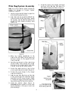
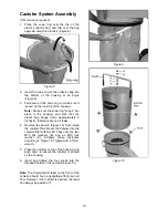
Page 9: ...wn on the collector bag to make sure it seats on the inner lip of the housing 5 Position the plastic window in front so that you can easily see when collector bag is full 6 Connect the upper hanger to the hanger support bar Figure 6 7 Slide the loop of the filter bag over the hook on the upper hanger and mount the hanger assembly onto the hanger bracket Figure 4 Rotate the hanger so that the hook ...

Page 10: ...ely 3 inches so that there are no air leaks 4 Remove the handle Figure 10 from inside the canister filter Mount the handle onto the canister filter with two M10 hex nuts A two M10 flat washers B and an M10 lock washer C Arrange these fasteners according to Figure 10 Tighten with a 17mm wrench 5 Place the canister on top of the housing and push down to ensure the canister is seated on the housing 6...

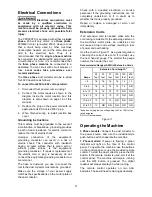
Page 11: ...pment grounding conductor to a live terminal The hose or ductwork you use to connect the tool to the dust collector must also be grounded Make sure the voltage of your power supply matches the specifications on the motor plate of the dust collector Check with a qualified electrician or service personnel if the grounding instructions are not completely understood or if in doubt as to whether the to...

Page 12: ...fore turning it OFF and removing plug from power source Failure to comply may cause serious injury Cleaning the Filter Bags Wearing a particle mask or respirator for protection against fine dust particles during cleaning is highly recommended During first use and after cleaning the filter bags may allow some dust to escape This is normal and will stop after a short period of time Clean both the fi...

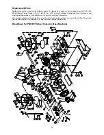
Page 13: ...p m CST Having the Model Number and Serial Number of your machine available when you call will allow us to serve you quickly and accurately Non proprietary parts such as fasteners can be found at local hardware stores or may be ordered from Powermatic Some parts are shown for reference only and may not be available individually Breakdown for PM1900TX Dust Collector Base Machine ...

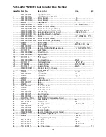
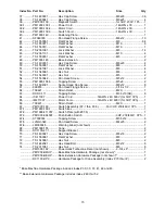
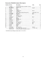
Page 14: ...RC 104 Seal 1 8 5 DCRC 103 Switch Plate 1 8 6 PM1900 108 6 Pan Head Screw M5x8 4 8 7 DCRC 102 Flat Head Screw 1 8 x 1 4 3 8 8 ST039304 Tapping Screw M3 5x12 AB 6 8 9 DCRC 111 Tapping Screw M4x10 1 PM1900 108 10 Display Label not shown 1 9 420051 Motor Gasket 1 10 431006 Impeller Dia 14 1 11 PM1900 111 Impeller Plate 8 1 12 499025 Inlet Port 3 4 1 13 420203 Inlet Cap 2 14 431034 Rubber Gasket 1 15 ...

Page 15: ...1 2 1 62 709421 Strain Relief M20 1 63 DCRC 111 Tapping Screw M3 5x10 AB 6 64 IC411007 Power Cord 14AWG x 4C 600V for 3HP 3Ph 1 65 IM411007 Motor Cord 14AWG x 4C 600V for 3HP 3Ph 1 66 709421 Strain Relief M20 1 67 PM1900 160 Switch Assembly 67 1 thru 67 6 For 3HP 230 460V 3Ph 1 67 1 PM1900 160 1 Switch Box 1 67 2 PM1900 411057 Switch Plate with 67 6 1 67 3 PM1900 994507 Push Button Switch 3HP 230 ...

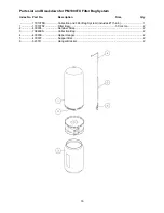
Page 16: ... Index No Part No Description Size Qty 1791075B Collection and Filter Bag System includes 1 thru 6 1 1 1791075F Filter Bag 30 micron 2 2 430005 Retainer Strap 2 3 708699A Collection Bag 2 4 430039 Upper Hanger 2 5 430037 Support Bar 2 6 523011 Hanger Bracket 2 ...

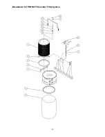
Page 17: ...17 Breakdown for PM1900TX Canister Filter System ...

Page 18: ... 2 9 TS 1550071 Flat Washer M10 2 10 331050 Handle 1 11 331051 Soft Grip Handle 2 12 TS 2361101 Lock Washer M10 1 13 BR000052 Rivet 5 2 3 14 331014 Bracket 1 15 150623 Rubber Mount 1 16 TS 1540041 Hex Nut M6 8 17 331052 Shaft 1 18 TS 1482041 Hex Cap Screw M6x20 4 19 TS 2361061 Lock Washer M6 4 20 TS 1550041 Flat Washer M6 4 21 331012 Scraper 2 22 331017 Plate 2 23 331015 Plate 2 24 TS 1482021 Hex ...

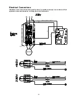
Page 19: ...and electrical wiring must be done by qualified person s in accordance with all applicable codes and standards including fire rated construction M O T O R POWER SUPPLY CORD MOTOR CORD 1 2 3 4 2 3 0 V 1 1 5 V R S E BLACK WHITE GREEN RED YELLOW U V ...

Page 20: ... product requires further inspection the Technical Service representative will explain and assist with any additional action needed Powermatic has Authorized Service Centers located throughout the United States For the name of an Authorized Service Center in your area call 1 800 274 6846 or use the Service Center Locator on the Powermatic website More Information Powermatic is constantly adding ne...

Reviews:

Related manuals for PM1900TX