15
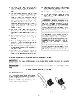
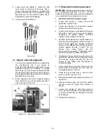
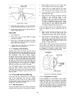
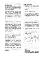
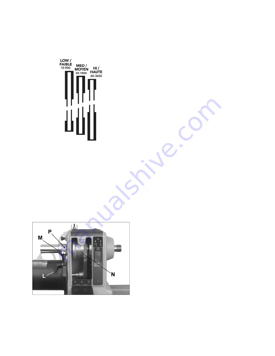
5. Loosen pivot lock handle (L, Figure 8-9) and
lower motor to tension belt. Be sure that V-
grooves of belt seat properly in corresponding
grooves of sheave. Do not overtension; a very
light pressure on the tension handle (M) is
adequate to prevent belt slippage.
6. Tighten pivot lock handle (L).
Figure 8-8
8.9
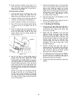
Sheave and belt alignment
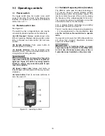
1. The motor and spindle sheaves are aligned by
the manufacturer, but if any service is
performed that affects their alignment it is very
important that they be realigned. To realign
them, loosen two set screws on spindle sheave
(one is shown at N, Figure 8-9) with a hex key,
and nudge spindle sheave into proper position.
Retighten both set screws.
2. When sheaves and belt are properly aligned,
there should be no unusual pulsing sounds or
noise coming from the belt.
Figure 8-9: sheave/belt alignment
8.10
Sheave/drive belt replacement
IMPORTANT:
Replacing spindle sheave or belt can
be a challenging procedure. If you do not feel
confident performing this action, take the headstock
to an authorized Powermatic service center.
1. Disconnect
lathe
from power source.
2. Loosen lock handle (L, Figure 8-9) and lift
handle (M) to raise motor.
3. Tighten lock handle (L) to hold motor in raised
position. Slip belt off lower pulley.
4. Loosen two set screws on handwheel (P, Figure
8-9) with a 3mm hex wrench, and unscrew
handwheel off spindle (NOTE: Left-hand
threads; rotate clockwise to loosen).
5. Tap left end of spindle with a rubber mallet, or a
steel face hammer against a block of wood, to
push it to the right, just enough to remove
sheave or belt. (
Never
use a steel face hammer
directly against spindle.) Prevent the top
sheave from being forced into the
sensor/encoder assembly; if necessary loosen
sheave set screws and slide it to the left.
6. If replacing sheave, loosen two set screws (N,
Figure 8-9), and slide sheave off spindle. Install
new sheave,
loosely
securing the two set
screws at first. Make sure the sheave is
oriented properly.
7. Push spindle back into place. Make sure the
sensor collar is positioned over the sensor for
the digital readout to function.
8. Check for any spindle play or “runout” at this
point. If it exists, see
sect. 13.0
.
9. Reinstall handwheel and tighten set screws (P,
Figure 8-9).
10. Align new sheave (see
sect. 8.9)
then tighten
two set screws (N, Figure 8-9) securely on
sheave.
11. Loosen lock handle (L) and allow motor to
lower. Do not over-tension; a very light pressure
on tension handle (M) is adequate to prevent
belt slippage.
12. Tighten lock handle (L).
Summary of Contents for PM2014
Page 27: ...27 15 1 1 PM2014 Headstock Assembly Exploded View ...
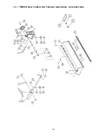
Page 30: ...30 15 2 1 PM2014 Bed Toolrest and Tailstock Assemblies Exploded View ...
Page 35: ...35 16 0 Electrical connections PM2014 Lathe cont next page ...
Page 36: ...36 cont ...
Page 38: ...38 This page intentionally left blank ...
Page 39: ...39 This page intentionally left blank ...
Page 40: ...40 427 New Sanford Road LaVergne Tennessee 37086 Phone 800 274 6848 www powermatic com ...


