6
4.0
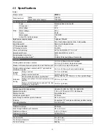
Specifications
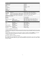
Table 1
Model number
PM2014
Stock numbers
Lathe 1792014
Stand (optional accessory)
1792014S
Motor and Electricals
Motor
Type Totally-enclosed,
fan-cooled
Horsepower 1
HP
Motor phase
3 PH
Motor voltage
230 V
Cycle 60
Hz
Motor speed
1720 RPM
Listed FLA (full load amps)
3 A
Input power requirements
1-phase, 120-volt
Drive system
Poly V belt, E-type inverter drive, 3-step pulley
Operating switch
Remote with magnetic base
VFD input amperage
13A, 1PH
VFD output to motor
3A (3PH)
Power cord and plug
SJT 3x14AWG 300V, 7 ft., 5-15P
Remote switch cord
AWM 24AWG 300V, 6-1/2 ft.
Recommended circuit size
1
15
A
Sound emission without load
2
75 dB at 20 inches (508mm) from motor
Capacities
Working distance between centers
19-1/4 in. (489mm) stop bolt installed
20-1/4 in. (514.4mm), stop bolt removed
Maximum distance between spindle face and tailstock quill 23 in. (584 mm), stop bolt removed
Working distance between centers with 13”
optional
bed
extension mounted
32-1/4 in. (819mm) with stop bolts installed
Inboard
turning
Swing over bed
14-1/4 in. (362 mm)
Swing over toolrest base
10-3/4 in. (273 mm)
Outboard
turning
Recommended maximum spindle load
3
356 kg (786 lbs.) at 100mm (4 in.) from spindle flange
Swing over
optional
13in. bed extension in low
position
20-1/4 in. (514 mm)
Swing over toolrest base on
optional
13in. bed
extension in low position
16-3/4 in. (425 mm)
Headstock and spindle
Spindle speeds (3 belt positions)
Variable: 15~900, 30~1800, 60~3600 RPM
Spindle thread size
1-1/4 in. (31.75 mm) x 8 TPI, RH threads
Spindle direction
Forward/reverse
Headstock spindle taper
#2 Morse
Hole through headstock spindle, diameter
3/8 in. (9.5 mm)
Indexing
24 positions (15° workpiece rotations), positive locking
Faceplate diameter
3 in. (76.2 mm)
Tailstock
Tailstock quill taper
#2 Morse
Hole through tailstock quill, diameter
3/8 in. (9.5 mm)
Tailstock quill travel
4-1/4 in. (108 mm)
Tailstock quill thread
ACME 5/8 in-11
Tool rest
Tool rest width
8 in. (204 mm)
Tool rest post diameter
1 in. (25.4 mm)
Tool rest locking
Bushing
Summary of Contents for PM2014
Page 27: ...27 15 1 1 PM2014 Headstock Assembly Exploded View ...
Page 30: ...30 15 2 1 PM2014 Bed Toolrest and Tailstock Assemblies Exploded View ...
Page 35: ...35 16 0 Electrical connections PM2014 Lathe cont next page ...
Page 36: ...36 cont ...
Page 38: ...38 This page intentionally left blank ...
Page 39: ...39 This page intentionally left blank ...
Page 40: ...40 427 New Sanford Road LaVergne Tennessee 37086 Phone 800 274 6848 www powermatic com ...


