background image


13

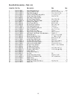
Rout-R-Lift Assembly – Parts List 

Index No.  Part No. 

Description 

Size 

Qty


1 ............... XLIFT-F0001 ............Flat Head Cap Screw................................... 1/4-20 x 3/4 .................... 28 
2 ............... PLIFT-P0003-1 ........Aluminum Main Plate ................................... 14-3/4 x 11-3/4 x 1/4 ......... 1 
3 ............... XLIFT-S0001-1 ........Steel Side Supports ..................................... 1/2 x 1/2 x 13-1/4 .............. 2 
4 ............... XLIFT-E0001-1 ........Aluminum Shaft Mounting Block .................. 1 x 1-1/2 x 10.1 ................. 1 
5 ............... XLIFT-F0002 ............Socket Head Cap Screw .............................. 1/4-20 x 7/8 ...................... 4 
6 ............... XLIFT-M0001 ...........Steel Drive Pulley Spindle ............................  ......................................... 1 
7 ............... XLIFT-M0006 ...........Bronze Flange Bearing ................................ 3/4 x 7/8 x 3/4 ................... 1 
8 ............... XLIFT-E0001-2 ........Drive Pulley Mounting Block ........................ 1 x 1-1/2 x 2 ...................... 1 
9 ............... XLIFT-M0011 ...........Rubber Timing Belt ...................................... 130 XL x 3/8 ..................... 1 
10 .............  XLIFT-M0005 ...........Drive Pulley (Delrin) ..................................... 20 XL x 3/8 ....................... 1 
11 .............  XLIFT-M0009 ...........Bronze Sleeve Bearing ................................ 3/4 x 7/8 x 3/4 ................... 4 
12 .............  XLIFT-F0005 ............Flat Head Cap Screw................................... 1/4-20 x 1 ......................... 4 
13 .............  XLIFT-E0001-3 ........Aluminum Bearing Mounts ........................... 1 x 1-1/2 x 4 ...................... 2 
14 .............  XLIFT-S0002-1 ........Steel Carriage Nut ....................................... 3/4 x 1 x 1-1/2 ................... 1 
15 .............  XLIFT-F0003 ............Nylon Insert Lock Nut .................................. 1/2-20 ............................... 1 
16 .............  XLIFT-E0002-1 ........Aluminum Carriage Bracket ......................... 3/8 x 3 x 8-1/2 ................... 1 
17 .............  XLIFT-F0006 ............Half Dog Pt. Set Screw (Anti-Backlash)........ 1/4-20 x 1 ......................... 1 
18 .............  XLIFT-M0012 ...........Rubber Washer ........................................... 1/2 x 1-1/16 x .093 ............ 1 
19 .............  XLIFT-M0003 ...........Brass Anti-Backlash Nut .............................. 1 x .450 x 1/2-20 ............... 1 
20 .............  XLIFT-M0004 ...........Threaded Pulley (Delrin) .............................. 20 XL w/ 1/2-20 ................ 1 
21 .............  XLIFT-F0004 ............Socket Head Cap Screw .............................. 1/4-20 x 1 ......................... 4 
22 .............  XLIFT-S0001-2 ........Carriage Mounting Block.............................. 1/2 x 1/2 x 3 Steel ............. 2 
23 .............  XLIFT-E0002-2 ........Aluminum Carriage Gusset .......................... 3/8 x 2-1/2 x 3 ................... 2 
24 .............  XLIFT-P0002 ...........Aluminum Carriage Plate ............................. 7.9 x 8-1/2 x 3/16 .............. 1 
25 .............  XLIFT-M0007 ...........Bronze Thrust Washer ................................. 9/16 x 1-1/4 x 1/16 thk ...... 1 
26 .............  XLIFT-M0042 ...........Carriage Lead Screw ...................................  ......................................... 1 
27 .............  XLIFT-M0008 ...........Bronze Flange Bearing ................................ 1/2 x 5/8 x 3/4 Lg .............. 1 
28 .............  XLIFT-M0017-1 ........Phenolic Insert Ring .................................... 1-1/2 hole opening ............ 1 
29 .............  XLIFT-M0016-1 ........Insert Wrench ..............................................  ......................................... 1 
30 .............  XLIFT-M0018 ...........Lift Handle (Arboron) ...................................  ......................................... 1 
31 .............  XLIFT-M0015 ...........Hex Key ...................................................... 1/4 .................................... 1 
32 .............  XLIFT-F0007 ............Socket Head Cap Screw .............................. 1/4-20 x 1-1/4 ................... 1 
33 .............  XLIFT-M0041-1 ........Phenolic Lift Handle Knob ............................ 1/4" Cored Hole ................ 1 
34 .............  XLIFT-P0009 ...........Master  Ring .................................................   .........................................  1 
35 .............  XLIFT-P0011 ...........Master Ring Clamp ......................................  ......................................... 6 
36 .............  XLIFT-F0008 ............Oval Point Socket Set Screw ....................... 1/4-28 x 1/4 .................... 10 
37 .............  XLIFT-P0012 ...........Starter  Pin ...................................................  ......................................... 1 


Summary of Contents for Rout-R-Lift

Page 1: ... Manual Rout R Lift and Fence Assembly Item No 6682004 Powermatic 427 New Sanford Rd LaVergne TN 37086 Part No M 0460261 Ph 800 274 6848 Revision D3 01 2014 www powermatic com Copyright 2014 Powermatic This pdf document is bookmarked ...

Page 2: ...ermatic website More Information JET Wilton and Powermatic are consistently adding new products For complete up to date product information check with your local distributor or visit the JET Wilton or Powermatic website How State Law Applies This warranty gives you specific legal rights subject to applicable state law Limitations on This Warranty JET WILTON AND POWERMATIC LIMIT ALL IMPLIED WARRANT...

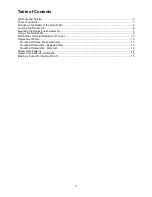
Page 3: ...ounting the Deluxe Fence Assembly 7 Using Your Rout R Lift 9 Modification for Height Adjustment Tension 10 Replacement Parts 10 Rout R Lift Deluxe Fence Assembly 11 Rout R Lift Assembly Exploded View 12 Rout R Lift Assembly Parts List 13 Router Hole Patterns 14 Router Hole Patterns continued 15 Making a Cut out for the Rout R Lift 15 ...

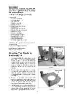
Page 4: ...ng Your Router to the Rout R Lift 1 Turn your Rout R Lift upside down on the table With the 5 32 hex wrench supplied remove the four 1 4 20 x 1 flat head cap screws Figure 1 and remove the aluminum carriage plate NOTE If the screws are blocked crank the Rout R Lift with the adjustment handle until all four screws are exposed 2 Remove the master ring from the carriage plate by first removing the si...

Page 5: ...e screws you removed from your router or the longer screws which you acquired attach the master ring to your router Fig 3 Lightly secure the screws at first to ensure that the master ring will locate in the center of your router and then tighten securely 8 You must now re attach the master ring to the aluminum carriage plate With the carriage plate upside down in front of you slide the master ring...

Page 6: ...e ring 3 Clamp the sub base to the master ring and use the sub base holes as a template to drill the holes into the master ring Use a bit slightly larger than your sub base screws 4 Remove the clamps and flip the master ring over so the engraved side with the T and B is now face up 5 Countersink the holes to suit the router s flat head screws NOTE If the router you are mounting does not have flat ...

Page 7: ... install onto the fence support Fig 8 The holes are staggered for easy installation 3 Slide assembly along the fence support until it stops at the fence guard bridge Fig 9 Securely fasten the screws 4 Take the remaining three button head Phillips screw and perform steps 1 2 and 3 on the other side of the fence support 5 Install the 1 4 20 x 1 flat head screws and square nuts into the holes in the ...

Page 8: ...e adjustable fence guard to the bridge on the fence bracket with the two fence guard knobs Fig 12 7 Mount the assembled fence to the main plate of the ROUT R LIFT with one fence knob in each of the threaded holes in the top corners of the plate Fig 13 8 The vacuum attachment is sized to accept standard 2 1 4 vacuum hose or a dust collector adaptor see your local Powermatic dealer for adaptors To i...

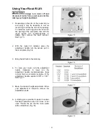
Page 9: ...he router bit installed place the adjustment handle into the access port in the main plate Fig 16 3 Bring the bit flush to the table top 4 To raise your router turn the adjustment handle clockwise to lower turn the adjustment handle counterclockwise Keep in mind that one complete revolution of the adjustment handle equals 0 050 or 1 20 See Fig 17 5 Make the desired height adjustment When your adju...

Page 10: ...er washer eases the rotation of the brass nut against the washer 4 Make certain when you have finished tightening the brass anti backlash nut that one of the slots on the nut is centered to the set screw This ensures that the set screw will protrude into the slot of the anti backlash nut See Fig 21 5 Snug the set screw then tighten the 1 4 20 hex nut that you loosened in step 2 Figure 19 Figure 20...

Page 11: ...T M0039 Fence Guard 1 8 Polycarbonate 1 5 XLIFT M0028 Guard Clamping Knob 2 6 PLIFT E0030 Aluminum Fence Extension 7 16 x 2 1 2 x 7 2 7 XLIFT F0028 Square Nut 1 4 20 10 8 XLIFT M0040 MDF Sub Fences 3 4 x 2 1 2 x 10 3 4 2 9 XLIFT F0017 Flat Head Screws 1 4 20 x 1 4 10 XLIFT E0032A Plastic Dust Collector Connector 1 11 TS 081A032 Pan Head Phillips Machine Screw 6 32 x 1 2 4 12 PLIFT E0032B Aluminum ...

Page 12: ...12 Rout R Lift Assembly Exploded View ...

Page 13: ...1 Aluminum Carriage Bracket 3 8 x 3 x 8 1 2 1 17 XLIFT F0006 Half Dog Pt Set Screw Anti Backlash 1 4 20 x 1 1 18 XLIFT M0012 Rubber Washer 1 2 x 1 1 16 x 093 1 19 XLIFT M0003 Brass Anti Backlash Nut 1 x 450 x 1 2 20 1 20 XLIFT M0004 Threaded Pulley Delrin 20 XL w 1 2 20 1 21 XLIFT F0004 Socket Head Cap Screw 1 4 20 x 1 4 22 XLIFT S0001 2 Carriage Mounting Block 1 2 x 1 2 x 3 Steel 2 23 XLIFT E0002...

Page 14: ... various routers as noted in Step 5 of Mounting Your Router Locate the name and correct model number of your router and then locate the holes in the master ring With a felt tip marker or pencil mark a line on the master ring for each hole you will be using for your router ...

Page 15: ...le from Powermatic that mount to a table saw and contain an opening designed specifically for the Rout R Lift If you wish to make your own opening in a table turn the Rout R Lift plate over and use it as a template to draw the lines for the cutout Be sure to rout a recess 3 8 deep or slightly deeper ...

Page 16: ...16 427 New Sanford Rd LaVergne TN 37086 Phone 800 274 6848 www powermatic com ...

Reviews: