background image

4

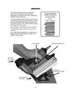
The Model 2000F nails down fl ooring from 
5/16” to 9/16” using the Powernail FLEX 
adjustable foot assembly that can be adjusted to 
fi t different fl ooring profi les.

To use the Model 2000F, properly position the tool 
on the fl ooring plank (See picture below). Pull up 
and hold the black safety trigger to activate the 
orange fi ring trigger.  The nailer will drive and set 
the nail at the correct angle.

Note: Modifying or altering the nailer in anyway 
can potentially cause injury and may void the 
warranty. 

The unique body design allows for different grip 
angles and has an adjustable exhaust port to 
redirect nailer exhaust.  

OPERATION

The Model 2000F

 installs tongue and 

groove fl ooring

from 

5/16” to 9/16” 

.

5/16"

(8 mm)

5/

16

"

3/8"

(9 mm)

3/

8"

1/2"

(12 mm)

1/

2"

1/

2"

.

.

.

.

.

.

.

.

.

9/16"

(14 mm)

Trigger-pull Activation!

Adjustable 
Exhaust Port

Adjustable 
FLEX Foot Assembly

Easy-to-remove
Gate Plate

Safety Trigger

Summary of Contents for Powernailer 2000F

Page 1: ...O MANUEL D INSTRUCTIONS ET D ENTRETIEN Read this manual before you use this Powernailer Follow all safety warnings and instructions If you are uncertain about the operation of the nailer call us direc...

Page 2: ...end of the warranty period POWERNAIL will perform all repair or replacements itself or through its authorized distributors POWERNAIL is not responsible for shipping labor or other direct or indirect...

Page 3: ...ified to assess the safe working condition of fastener driving tools Always make sure Nailer is empty of nails before connecting air hose so as to prevent any accidental discharge from occurring ONLY...

Page 4: ...e nailer will drive and set the nail at the correct angle Note Modifying or altering the nailer in anyway can potentially cause injury and may void the warranty The unique body design allows for diffe...

Page 5: ...on and set the compressors pressure regulator to the proper pressure Normal operating pressure should be adjusted between 70 110 psi based on fastener and wood being used 4 Connect the tool to the air...

Page 6: ...L GUIDE 44 and slide the channel guide out fully as shown in Figure 5 2 Place a full stick of 1 or 1 1 4 20 OPERATION continued Figure 5 Figure 6 Lock Fixed Channel Movable Channel Guide gage Powercle...

Page 7: ...ter performance and longer life The filter must have adequate flow capacity for the specific application 4 Keep tools clean for better and safer performance Use nonflammable cleaning solutions only if...

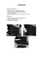
Page 8: ...3 Slide the gate plate down until it is free from the nose 6 Lift the gate plate 72 off 5 Inspect and clear any debris from the drive blade 27 and its path Reassembly 1 Install the the gate plate over...

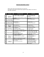
Page 9: ...Tool skips a fastener 1 Worn bumper 22 or damaged spring 57 2 Dirt in gate 50 3 Inadequate airflow to tool 4 Worn or dry O ring 17 on piston 5 Cylinder cap seal leaking 8 1 Replace bumper or pusher sp...

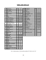
Page 10: ...0F8026 27 SAFETY TRIGGER S 09 20F8027 28 E RING S 09 20F8028 29 O RING n a 30 COVER n a 31 AIR PLUG n a 32 TRIGGER VALVE ASSEMBLY n a 33 SPRING n a 34 MAIN TRIGGER n a 35 HEX HEAD BOLT S 09 20F8035 36...

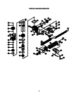
Page 11: ...11 MODEL 2000F SCHEMATIC A...

Page 12: ...roper length of Powercleats to use for various thicknesses of flooring Approximate vertical penetration of the Powercleat under the hardwood floor is shown for each application This is only a guide Re...

Reviews: