Powernet reserves the right to change the specification without notice
Created: JMa/TRä 07.06.2012/ Updated: 19.08.2015 HLi
437c5q
DATASHEET / USER MANUAL
SELECTION TABLE OF ADC4370 FEATURES
This table shows which
features are possible at the
same time.
IF N THEN then not possible.
Some of allowed combinations are
optional. Contact manufacturer or
your local distributor for further
details.
T
r
i
m
m
e
r
A
n
a
l
o
g
R
e
l
a
y
B
u
s
O
u
t
B
u
s
I
n
T
e
m
p
S
e
n
s
e
C
o
d
e
S
w
i
t
c
h
Trimmer adjustment
N
N N
N
Analog control (isolated)
N
N N
N
Relay alarm
N
BusOut (RS-232 control to slave)
N
BusIn
N N
Temp.comp.
N N
Sense
Customised charging algorithm
chargers with code Switch
N N
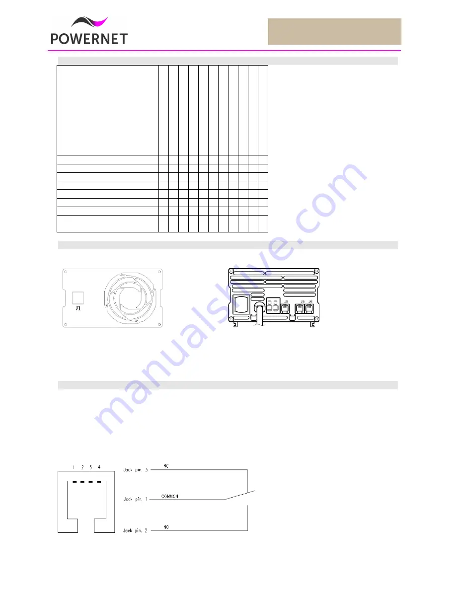
PIN CONFIGURATION, MODULAR CONNECTORS
ALARM RELAY MODELS,
type number example ADC4370/24H
If the unit is ordered with alarm relay, the potential free alarm output indicates if the charger’s output is healthy. The
alarm signal is activated in AC fail and charger fail cases. Both normally open and normally closed signals are
presented.
Pin Configuration, Modular connector J8 with relay alarm option
MODULAR JACK
Front view
CABLE
Black = common
Red = NO
Green = NC
RELAY
Isolation:
Technical data:
Output to Case: 500V
1A @ 24Vdc
Output to GND: 120V
0,5A @ 120Vac
If power is off the COMMON is connected to NC. When power is switched ON the COMMON is connected to NO
Front panel
J1
Analog input 0-5VDC
Rear panel
J8
RS-232 bus output, master-slave
Alternatively power fail relay alarm
J5
Temp.comp in temp.comp models, Sense option
Alternatively R-232 bus input, master-slave
J6
Optional external LED


