background image


11

Unpacking 


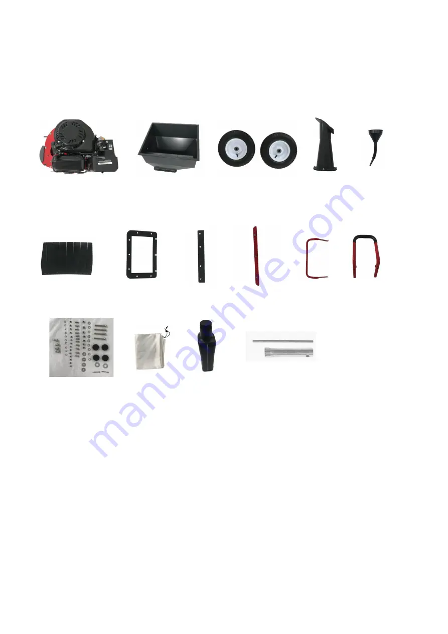
Unpack the chipper shredder and all its parts, and compare against the list below. Do not discard the 
carton or any packaging materials. Please call 1-800-791-9458 or E-mail us at 
support@amerisuninc.com if any parts are damaged or missing. 
 
Including:  


Engine 

  2 

Hopper 

Wheel 

  4 

Chipper chute 

Funnel 

  6 

Hopper Flap 

Hopper Gasket 

  8 

Batten 

Locking strip 

  10 

Handle 

11  Support leg 

  12 

Accessory bag for assembly 

13  Discharge Bag  

  14 

Oil bottle 

15  Spark plug wrench 


1                                                  2                                         3                                  4                    5 

6                                       7                              8                        9                            10                   11 

12                                     13                          14                             15 

Summary of Contents for PS1130

Page 1: ...D CHIPPER SHREDDER Model PS1130 Have product questions or need technical support Please feel free to contact us Website www Amerisuninc com www powersmartusa com Toll free 1 800 791 9458 M F 9 5 EST E...

Page 2: ......

Page 3: ...TECHNICAL DATA Gas powered chipper shredder Model PS1130 Engine type 4 Stroke OHV single cylinder with forced air cooling system Spark plug gap 0 027 0 031 0 7 0 8 mm Displacement 212cc Fuel type 87 o...

Page 4: ...ate on regular unleaded gasoline and may include the following emission control systems EM Engine Modifications and TWC Three Way Catalyst if so equipped SAFETY INFORMATION Before operating this chipp...

Page 5: ...e poisoning WARNING The exhaust from this product contains chemicals known to the State of California to cause cancer birth defects or other reproductive harm WARNING This engine may emit highly flamm...

Page 6: ...pper Chipper Chute or Discharge Opening when the machine is running Do not allow metal stone glass or other foreign objects to be fed into the Chipper Shredder Use a stick to push the tree limbs leave...

Page 7: ...particular type of equipment taking into account the working conditions and the work to be performed Use of the equipment for operations different from those intended could result in a hazardous situa...

Page 8: ...ngine and equipment maintenance Refueling Do not refill the fuel tank while the engine is running or hot Do not smoke or allow sparks flames or other sources of ignition around the equipment especiall...

Page 9: ...s manual before using this product Eye protection Wear eye protection when operating this equipment Hearing protection Use proper hearing protection when operating this equipment Risk of Respiratory I...

Page 10: ...10 KNOWING YOUR CHIPPER SHREDDER Handle Wheel Locks Fig 2...

Page 11: ...call 1 800 791 9458 or E mail us at support amerisuninc com if any parts are damaged or missing Including 1 Engine 2 Hopper 3 Wheel 4 Chipper chute 5 Funnel 6 Hopper Flap 7 Hopper Gasket 8 Batten 9 Lo...

Page 12: ...and bend the Cotter Pin over to secure the Wheels in place Secure the Support Leg 46 to the Engine using Bolts 45 Shock Absorbers 53 Large Flat Washers 54 See fig 3 2 Position the chipper chute over t...

Page 13: ...wn in the figure Pay attention to tighten See fig 6 5 Install the handle 7 with 4 lock nuts M6 5 and 4 bolts M6 16 6 to the hopper The bolt goes through the hopper To attach the Discharge Bag 55 lift...

Page 14: ...and is level 2 Close the Fuel Valve 3 Clean the top of the Dipstick and the area around it Remove the Dipstick by turning it counterclockwise and wipe it off with a clean lint free rag 4 The oil capac...

Page 15: ...e If any fuel is spilled make sure the area is dry before starting the engine 5 Avoid repeated or prolonged contact with skin or breathing of fuel vapor Keep out of reach of children Use fresh within...

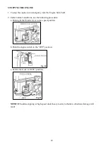
Page 16: ...nt during use Manual start 1 Turn the fuel cock to the ON position See fig 11 2 Turn the choke lever to the START position If the gasoline engine is hot turn the choke lever to the RUN position See fi...

Page 17: ...ed use a stick to push the material into the Shredder 1 Without putting your hands into Shredder on top slowly drop material into the Hopper one branch at a time The machine will pull the material in...

Page 18: ...ormal conditions use the following procedure a Push right the throttle lever to low speed position b Push the engine switch to the OFF position c Set the fuel cock to OFF position NOTICE Sudden stoppi...

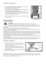
Page 19: ...serviced properly Many maintenance procedures including any not detailed in this manual will need to be performed by a qualified technician for safety If you have any doubts about your ability to safe...

Page 20: ...pping stage to avoid burn WARNING The spark plug must be tightened securely or it may become very hot to damage the engine AIR FILTER MAINTENANCE A dirty air filter can restrict air flowing into the c...

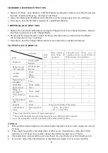
Page 21: ...or other severe circumstances clean the air filter element every 10 hours If necessary change the air filter element every 25 hours The maintenance period and the exact time hour the one which comes f...

Page 22: ...n according to following table when reuse after storing Storing time Maintaining procedure is commended in order to prevent starting difficult 1 month Don t need to prepare 1 2 month Drain the used ga...

Page 23: ...screwdriver handle 8 Turn Choke to RUN position Remove spark plug and pull the start handle several times to air out the chamber Reinstall spark plug and set Choke to START position 9 Replace Fuel Fi...

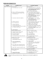
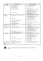
Page 24: ...g cap Engine stops when under heavy load 1 Dirty air filter 2 Engine running cold 1 Clean element 2 Allow engine to warm up prior to operatingequipment Engine knocks 1 Old or low qualitygasoline 2 Eng...

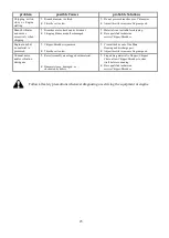
Page 25: ...pping blades are dull ordamaged 1 Material is not suitable for chipping 2 Have qualified technician serviceChipper Shredder Engine runs but no material is processed 1 Chipper Shredder isjammed 2 Throt...

Page 26: ...26 EXPLODED VIEW AND PARTS LIST...

Page 27: ...041 Spring washer 6 2 14 PS1130 014 Rotor Housing 1 42 PS1130 042 Engine Mounting Block 1 15 PS1130 015 Flat Washer 8 50 43 PS1130 043 Engine Flat Key 1 16 PS1130 016 Axle Assembly 1 44 PS1130 044 En...

Page 28: ...28 Engine explode view and part list...

Page 29: ...2 14 12101 Z810210 0000 GUIDE SEAL 1 15 12140 Z810210 00A0 HEAD SUBASSEMBLY CYLINDER 1 16 30010 Z010210 0000 PLUG SPARK 1 17 12131 Z950110 0000 GASKET CYLINDER HEAD 1 18 90502 1114 00 PIN 2 19 14071 Z...

Page 30: ...H700 SHROUD 1 48 28200 Z440110 H700 STARTER ASSY RECOIL 1 49 13510 Z440410 0000 FLYWHEEL SUBASSEMBLY 1 50 19352 Z440110 00A0 IMPELLER 1 51 28002 Z010310 0000 PULLEY STARTER 1 52 13501 Z010110 0000 NUT...

Page 31: ...ALVE RETURNING 1 74 16730 Z440810 LK00 COVER FUEL TANK 1 75 16652 Z010710 00A0 STRAINER FUEL 1 76 16620 Z440410 H70P TANK FUEL 1 77 16680 Z010210 0000 OUTLET SUBASSEMBLY FUEL TANK OIL 1 78 90685 Z0801...

Page 32: ...ited warranty To make a claim under this Limited Warranty you must return the entire power tool product transportation prepaid to PowerSmart The owner must include a legible copy of the original recei...

Reviews: