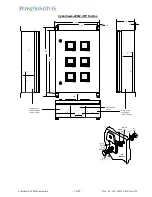
Cyberhawk-200M Installation
-
5 of 22 -
Doc. No: 202-003318-610 Rev A01
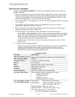
*Note: These CTs are listed to UL ANSI/IEEE C57.13 and additionally comply with the
requirements of UL916 with regard UL746 for polymeric material requirements and secondary
lead termination as specified above.
SYSTEM INSTALLATION CONFIGURATIONS
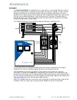
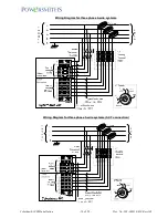
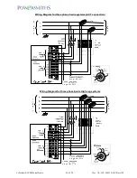
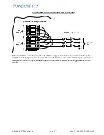
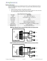
Prior to installation make a wiring diagram of the desired connections with reference to the
appropriate system configuration to be connected for each meter port. Note that wiring for
the different system configurations are illustrated in this bulletin. This will define the system
voltage connections and the number of CTs required.
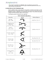
The following system configurations are supported:
Table of System Configurations
System Type
Diagram
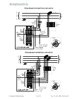
Reference Diagrams
Single Phase
(2-wire + GND)
Single Phase 2-Wire; 1-CT
2 x Single Phase from
single source
(2 x 2-wire + GND)
Split Phase 3-Wire; 2-CT
Split Phase
(3-Wire + GND)
Three Phase Open-Delta
(3-wire + GND)
Three Phase Delta
(3-wire + GND)
Three Phase 3-Wire; 2-CT
Three Phase 3-Wire; 3-CT
Three Phase Wye
(4-wire + GND)
Three Phase 4-Wire; 3-CT
Three Phase High Leg
Delta
(4-wire + GND)


