En
gli
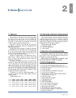
sh
Installation
3
3 : 1.Location
The intended use of k Series amplifiers is in a rack cabi-
nets. The ac mains wirings of the units shall be connected
to a power distribution panel inside the rack cabinet. in
order to limit the risk of mechanical damages, the amplifiers
must be fixed to the rack using both frontal and rear mount-
ing brackets. We recommends to use eight M6 or 12-24
uNc-2B screws for threaded holes or cage nuts.
install this amplifier as far as possible from radio tuners
and TV sets. an amplifier installed in close proximity of such
equipment may experience noise or generic performance
degradation. placing and using the amplifier for long periods
of time on heat generating sources will affect its performance.
avoid placing the amplifier on heat generating sources.
3 : 2.Cooling
install the amplifier in a well-ventilated location: the ven-
tilation openings must not be impeded by any item such as
newspapers, tablecloths, curtains, etc; keep a distance of
at least 50 cm from the front and rear ventilation openings
of the amplifier.
all powersoft amplifiers implement a forced-air cooling
system to maintain low and constant operating tempera-
tures. Drawn by the internal fans, air enters from the front
panel and is forced over all components, exiting at the back
of the amplifier.
The amplifier’s cooling system features “intelligent” var-
iable-speed Dc fans which are controlled by the heatsink
temperature sensing circuits: the fans speed will increase
only when the temperature detected by the sensors rises
over carefully predetermined values. This ensures that fan
noise and internal dust accumulation are kept to a strict
minimum.
Should however the amplifier be subject to an extreme
thermal load, the fan will force a very large volume of air
through the heat sink. in the extremely rare event that the
amplifier should dangerously overheat, sensing circuits
shut down all channels until the amplifier cools down to a
safe operating temperature. Normal operation is resumed
automatically without the need for user intervention.
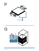
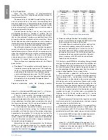
k Series amplifiers can be stacked one on top of the other
due to the efficient cooling system they are equipped with.
There is however a safety limit to be observed: in case
a rack with closed back panels is used, leave one rack unit
empty every four installed amplifiers to guarantee adequate air
flow (see
panel q, p. 18
).
3 : 3.Cleaning
always use a dry cloth for cleaning the chassis and the
front panel. air filter cleaning should be scheduled according
to the dust levels in the amplifier’s operating environment.
Disconnect the AC mains source before
attempting to clean any part of the amplifier
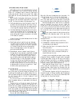
in order to clean the vent filters you need to remove the
front cover: never attempt to open any other part of the unit.
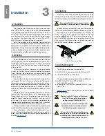
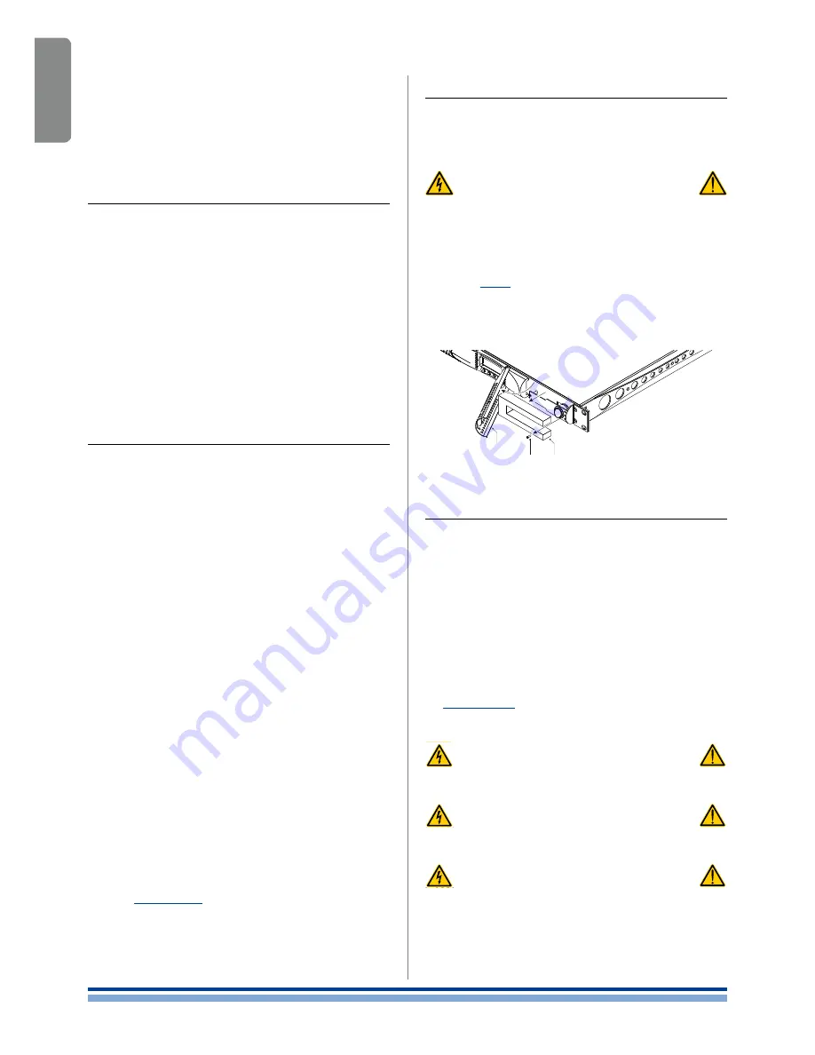
By means of a screwdriver phillips pH1, unscrew the
screws that lock the left and right cover grils on the front
panel (ref.
FiG. 1
), gently lift the covers and remove the fil-
ters. You may use compressed air to remove the dust from
filters, or wash it with clean water: in the latter case ensure
that the filters are dry before reassembly.
3 : 4.AC mains supply
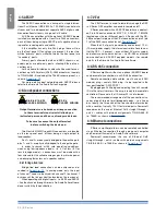
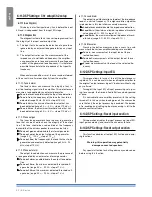
The ac Main connection is made via the
f
f
aMp cpc 45a connector in k6, k8, k10 and k20;
f
f
iEc c20 connector in k3 and k2.
The power cord type provided with the amplifier are
f
f
Lapp OLFLEX191 3G6 / SJT 3XaWG10
for k6, k8, k10 and k20.
f
f
Bahoing SJT 3x16aWG or i-sheng SGiS 3G 1,5 mm
2
for k3 - k2.
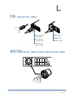
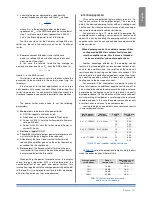
panel L, p. 13
shows how to connect the mains power
cable to the amplifier.
Make sure the AC mains voltage used
is within the acceptable operating
voltage range: 115V-230V ±10%.
It is important to connect the ground
for safety, do not use adapters that
disable the ground connection.
Connection to the mains shall be done
only by a electrotechnical skilled person
according the national requirements of
the countries where the unit is sold.
CLASS3
WIRING
CLASS3
WIRING
CLASS3
WIRING
CLASS3
WIRING
CLASS3
WIRING
CLASS3
WIRING
cover grill
screw filter
FIG. 1: Cleaning air filters.
22 | K Series
Summary of Contents for K2 DSP+AESOP, K3 DSP+AESOP
Page 4: ...Page intentionally left blank 2 K Series...
Page 8: ...A K2 K3 K2 DSP AESOP K3 DSP AESOP 465 32 2 496 456 5 9 482 439 44 32 6 K Series...
Page 88: ...Page intentionally left blank 86 K Series...
Page 89: ...Page intentionally left blank Specifications 87...
Page 90: ...Page intentionally left blank 88 K Series...
Page 91: ......

