background image


Load Break Switch Control                                       

ERT-200S 

4.4.


Remote Communication Port ....................................................................................................... 25


4.5.


Digital Input /Output ..................................................................................................................... 26


4.6.


DOOR Port ........................................................................................................................................ 26


4.7.


AUX. DI/DO ...................................................................................................................................... 26


4.8.


Motor Output Port ......................................................................................................................... 26


4.9.


Power Supply Input (AC Input) .................................................................................................... 26


4.10.


Battery Port .................................................................................................................................. 27


4.11.


Main Power Switch ...................................................................................................................... 27


4.12.


ETHERNET Connector ................................................................................................................. 27


5.


Operator Control Panel ........................................................................................................ 28


5.1.


Description ....................................................................................................................................... 28


5.2.


Construction ..................................................................................................................................... 32


5.2.1. 

Operation .................................................................................................................................................................................. 32 

5.2.2. 

Menu Control .......................................................................................................................................................................... 33 

5.2.3. 

Other Control .......................................................................................................................................................................... 33 

5.2.4. 

Fault Indication ....................................................................................................................................................................... 34 

5.2.5. 

  Line Status Indication ....................................................................................................................................................... 34 

5.2.6. 

SECTION Status ...................................................................................................................................................................... 35 

5.2.7. 

System Status .......................................................................................................................................................................... 35 

5.2.8. 

AC/HANDLE LOCKED/GAS LOW/Battery Status ..................................................................................................... 36 

5.2.9. 

CONSOL Port .......................................................................................................................................................................... 36 

5.3.


Operation Manual (LCD instruction) ........................................................................................... 37


5.3.1. 

LCD Screen ............................................................................................................................................................................... 37 

5.3.2. 

Control button ........................................................................................................................................................................ 37 

5.3.3. 

Menu structure tree ............................................................................................................................................................. 38 

5.4.


LCD Menu Use ................................................................................................................................. 39


5.4.1. 

Initial Screen ............................................................................................................................................................................ 39 

5.4.2. 

Main Menu ............................................................................................................................................................................... 40 

5.4.3. 

Setting Menu .......................................................................................................................................................................... 41 

6.


Fault Indication ...................................................................................................................... 43


6.1.


Fault Indication ................................................................................................................................ 43


Summary of Contents for ERT-200S

Page 1: ...Feeder Remote terminal Unit ERT 200S Manual www powersys kr...

Page 2: ...Digital Process 11 2 4 1 Digital Signal Controller DSCs 11 2 4 2 Analog Digital Conversion 12 2 4 3 Function 12 2 5 Function Block Diagram 13 2 6 Fault Detect and Sectionalizing Functions 14 2 7 Powe...

Page 3: ...n 28 5 2 Construction 32 5 2 1 Operation 32 5 2 2 Menu Control 33 5 2 3 Other Control 33 5 2 4 Fault Indication 34 5 2 5 Line Status Indication 34 5 2 6 SECTION Status 35 5 2 7 System Status 35 5 2 8...

Page 4: ...Time Setting 56 7 1 5 Line Open Setting 57 7 1 6 Sync Check Setting 58 7 1 7 Sectionalize Setting 59 7 1 8 SEF Setting 60 7 1 9 Under Frequency Setting 61 7 1 10 Over Frequency Setting 62 7 1 11 Under...

Page 5: ...ntrol ERT 200S 8 2 Status view 90 8 3 Counter view 91 8 4 Alarm View 91 This menu displays controller Fault detection 91 8 5 System Information 92 9 Event Event Log 93 Appendix 1 Drawings 96 1 Enclosu...

Page 6: ...zedfor remote control and automation systems ERT 200Smonitors not only electric qualityof distribution line but also provides Section operation in case of fault occurring and minimize its fault area A...

Page 7: ...wer Factor Frequency Phase difference between source side and load side voltage Ground Fault SEF Inrush Detect Sync Check Sectionalize Control Manual LBS Open Close at local or remote operator Place B...

Page 8: ...I Event I O Event System Event Control Event Measure Event Demand Current Power Daily Max Current Power Waveform Recording Storage 8 Fault Waveforms of 10 cycles Sampling ratio 32 Sample Cycle 10 Cycl...

Page 9: ...rval 5 years Earthing 10mm earth stud Modem Modem may be fitted by the manufacturer or by the utility for remote communications Space power and data interfaces are provided within the control cubicle...

Page 10: ...E SWC test 3 Vibration1 to 1 5 5 fast saturation 1 2 50 IEEE C37 90 2 1987 IEEE Test Test use standard relay system for Radio Electromagnetic Interface that comes from Transceiver 10 V m 150 and 450 5...

Page 11: ...te Output 240Vac 16A 30Vdc 16A Aux DO 1 4 250Vac3A 30Vdc 3A Input Input 8 channel Dry Contact Input Type 2 4 Digital Process 2 4 1 Digital Signal Controller DSCs DSP Processor Feature High Performance...

Page 12: ...Digital Conversion ADC Feature 16 Bit A D Converter Anti aliasing analog filter One gain channel for each current input effective 16 bit resolution for current measurements 2 4 3 Function Self Diagnos...

Page 13: ...13 Load Break Switch Control ERT 200S 2 5 Function BlockDiagram...

Page 14: ...Pickup 5 85 Default 10 Step 1 Direction MTA 0 359 deg Default 0 deg step 1 deg Ground Fault Detection Earth Fault Threshold Current Setting Range Pick up Current 5 to 900 A Default 60A step 1A Definit...

Page 15: ...Faults to trip Fault count 1 to 3 default 2 step 1 Sequence reset time 20 240 s Default 30s step 1s SEF Sensitive Earth Fault Detection Sensitive Earth Fault Threshold Current Setting Range Pick up Cu...

Page 16: ...ng Range 0 1 20 0 sec Default 1 0s step 0 1s 2 7 Power System Measurements Current measurement RMS A Phase angle Ia Ib Ic In Sequence Component I1 I2 I0 Reading Range 2 12 500 A External CT Ratio 1 00...

Page 17: ...3P3L default 3P4L Rated Voltage 3800 26000 V CT Ratio 100 2000 A default 1000 A NCT Ratio 100 2000 A default 1000 A CT Direction FWD REV default FWD Interlock 1 Live Load Volt Interlock Yes No No 2 Sy...

Page 18: ...onitor was built in FRTU IEC60870 5 101 Address size is configurable Two time tag formats are selectable 24 bit or 56 bit Single character for NACK is supported Cyclic update of measurements data Clas...

Page 19: ...default 10s D L Confirm Yes No Sometime default Sometime A L retry 0 2 default 0 A L Time Out 0 255 sec default 15 sec InitUnsol Yes No default No Unsol Class1 Enable Disable default Disable Unsol Cla...

Page 20: ...Size 1 3 Default 1 COTA Address Size 0 2 Default 2 Link Mode Unbalance Balance Default Unbalance IEC104 T0 Off PRD 1 255 default 30 sec T1 Ack PRD 1 255 default 15 sec T2 S frame PRD 1 255 default 10...

Page 21: ...be displayed in the R Manager SW package in chronological order allowing the sequence of events to be viewed Events are also made available spontaneously to an Modbus RTU or DPN 3 0 compliant control...

Page 22: ...ol ERT 200S Waveform Event Record Event List Description Waveform Waveform Recording Storage 8 Fault Waveforms of 10 cycles Sampling ratio 32 Sample Cycle 10 Cycles Max 8 fault waveforms can be captur...

Page 23: ...tion The ERT 200Sincludes the following major components Inclusion with a local communication port and LCD display keypad CPU System Controller Board Process I O board Internal mounting brackets and b...

Page 24: ...d Break Switch Control ERT 200S 4 Input output Connector ERT 200Sprovides terminals connector to connect control and modem The terminal arrangement is as Bellows Figure4 1 Connectors on the Side of ER...

Page 25: ...modem power supply terminal Modem power Fuse socket DC 12V Options 4 2 Current Input Current connecters with phase A and follows by B C N Aux1 Aux2 is spare Aux Port and not assign 1 2 3 4 ZCT2 ZCT1...

Page 26: ...GAS LOW 52B 52A DI_COM 4 6 DOOR Port DOOR OPEN SENSING PORT 4 7 AUX DI DO Aux DI DO 14 13 12 11 10 9 8 DO4_2 DO3_2 DO2_2 DO1_2 DI_COM DI3 DI4 7 6 5 4 3 2 1 DO4_1 DO3_1 DO2_1 DO1_1 DI_COM DI1 DI2 4 8 M...

Page 27: ...eak Switch Control ERT 200S 4 10 Battery Port Battery charging output port DC 27V terminal Fuse socket Fuse 15A 4 11 Main Power Switch Main Power Switch connection terminal 4 12 ETHERNET Connector 10...

Page 28: ...The Control Panel consists of a four line Liquid Crystal Display LCD and keypad with switches and Light Emitting Diodes LEDs which are used to select and monitor the functionality of the LBS Onthefron...

Page 29: ...PHASE SEF 2 SYNC FAILED 3 REVERSE POWER Indicates all the Fault detection settings currently in use e g Fault Settings and Sectionalizing 5 1 AC POWER Indicates the external AC power supply status 2 H...

Page 30: ...mation check mechanism To manually and locally control the LBS CONTROL SELECT button should be pushed down to make the corresponding LED on and this CONTROL SELECT function can be expanded to the sche...

Page 31: ...31 Load Break Switch Control ERT 200S H RS 232C PORT RT 200 is an advanced personal computer based software package to allow off line and on line monitoring and control of a LBS via RS232 port...

Page 32: ...k first if the control position is Local LED ON CONTROL SELECT button is a two phase safety confirmation check mechanism To manually and locally control the LBS CONTROL SELECT button should be pushed...

Page 33: ...and connects a load resister to battery and check the charging circuit Remote CONTROL Button Local Remote When LED is ON Remote and Local operation are all available When LED is OFF only Local operat...

Page 34: ...t is unbalanced control is still available Operator shall decide an operation Phase Voltage Indicator LiveLine LED Source side and load side live line status are indicated More than one phase voltage...

Page 35: ...nostic is displayed RUN LED Green indicates that ERT 200S has passed the internal diagnostic test and does not have any problem RX TX RTS LED Red indicates the communication state of ERT 200S RUN It i...

Page 36: ...on the Manual Lock handle with a hookstick When locked the mechanism cannot be tripped or closed either mechanically or electrically GAS LOW Check that the gas low alarm is showing on the operator con...

Page 37: ...l setting value It is used for menu selection or setting change In menu selection screen this button is used for menu selection function In setting change status moves to menu mode by pressing this bu...

Page 38: ...38 Load Break Switch Control ERT 200S 5 3 3 Menu structure tree Figure Menu Tree Structure...

Page 39: ...ding of the user To move to other initial screen press UP DOWN button Press MENU button in initial screen to move to Main menu Initial Screen 1 Startup Screen Indicate the Model version status 2 Push...

Page 40: ...s MENU button it is moved into Main menu If press MENU button in main menu it is moved to the initial menu Main menu has sub menu as below Main Menu Screen Main menu is composed of 4 submenus Push the...

Page 41: ...erate Set Phase Fault Set 2 Locate the cursor on Phase by using choose UP DOWN key and then press the ENTER button to change the set point 3 Change in new setting point by using UP DOWN button By pres...

Page 42: ...42 Load Break Switch Control ERT 200S...

Page 43: ...current event is generated for each element that have picked up A peak current event is a record of the maximum current measured between fault pickup and fault reset 6 1 Fault Indication Distribution...

Page 44: ...oser R1 in the line and L2 L3 indicate fault at the time iii DAS decided the fault section and opened L3 L4 then closed R1 L5 L5 may be energized from the loop tie switch backward Fig 6 1 Fault detect...

Page 45: ...amples which stored 10 cycles 32 samples cycle V Low Level V FI PickUp FI Fault Fig 6 4 FI Fault Scheme Direction Detection Direction detection is to restrict fault indication only on faults to a desi...

Page 46: ...the fault detection pickup level is changed by the times of Cold load Multiplier 1 10 and this is in the instantaneous element If the transient current goes down and retains below the pickup level wit...

Page 47: ...On the non grounded network it is hard to detect fault current because ground current of non grounded network is so small Therefore FTU P200 is designed to measure zero sequence values from either ext...

Page 48: ...ty section from the distribution Feeder automatically before the Recloser or reclosing relay of CB lockouts The condition to open automatically is the fault count FTU detects and counts the fault and...

Page 49: ...ly when at least one phase has normal voltage It has hysteresis characteristics Voltage On level Off level and Delay time settings are needed for this function 6 7 Phase Sync Check ERT 200Smonitors th...

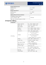
Page 50: ...ove to this menu by pressing ENTER Operation Setting menu has the following submenu 7 1 1 Phase Fault Setting Range Step Def Unit Min Max Function Use No Yes No PickUp Current 5 900 1 400 A Detection...

Page 51: ...nged New Set selected YES NO by using UP DOWN and by pressing ENTER button you can changed new setting value Phase Fault Pick Up Current Range 5 1300 Default 400A Step 1A Set Pick Up Current Setting F...

Page 52: ...Default No Step Set YES No of direction Detection when occurs Inrush Restraint Phase Fault Direction Function use Range No Use Use Default Use Step Set YES No of direction Detection when occurs Inrus...

Page 53: ...85 10 1 Direction MTA 0 359 0 1 deg Ground Fault Function use Range Default Step Set Use No Use of direction Detection when occurs Ground fault Ground Fault Pick up Current Range 2 650 A Default 200...

Page 54: ...lt Step Set Use No Use of direction Detection when occurs Ground fault Ground Fault Direction Function use Range No Use Use Default Use Step Set YES No of direction Detection when occurs Inrush Restra...

Page 55: ...c 2nd Harmonic Set Range 5 50 Default 20 Step 1 Set 2nd harmonic Detection Time Set Range 0 02 1 00 sec Default 0 02 Default 0 02 Set Detection time of Inrush detect element Function use Range Default...

Page 56: ...Set Range 100 1000 Default 500 Step 10 Function use Range Default Step Set Use No Use of direction Detection when occurs Inrush detect 7 1 4 FI Reset Time Setting Range Step Def Unit Min Max FI Reset...

Page 57: ...Phase will be detected If the voltage on detected phase rises to the Volt ON Level setting the Loss of Phase is released immediately Range Step Def Unit Min Max On Voltage 50 90 1 80 Off Voltage 35 8...

Page 58: ...t 30 Deg Step 1 Deg Set an alarm on the source side and load side voltage phase Sync Check Function use Range 0 1 300 0 sec Default 0 4 Default 0 1 sec Set Delay time of Line Sync detect element Sync...

Page 59: ...IT VT Default VIT Step Select mode to detect operation as voltage or current or voltage only Sectionalize Fault count Set Range 1 3 Default 2 Step 1 The number of supply interrupts counted exceeds the...

Page 60: ...Step Def Unit Min Max I Pick Up 2 20 1 5 A V PickUp 10 80 1 30 V Angle 0 90 1 90 Deg Detection Time 0 1 300 0 0 1 0 1 sec Inrush Rest No Yes No Function Use No Yes No SEF Pick up Current Set Range 2 2...

Page 61: ...aint Set Range Yes No Default No Step Set YES No of direction Detection when occurs Inrush Restraint SEF Function use Range Default Step Set Use No Use of direction Detection when occurs Ground fault...

Page 62: ...1 Set pickup voltage UFR Delay Time Set Range 0 1 20 0 sec Default 1 0 s Step 0 1 s Set Delay Time UFR Function use Range Yes No Default No Step Set Use No Use of direction Detection when occurs Grou...

Page 63: ...efault 80 Step 1 Set pickup voltage OFR Delay Time Set Range 0 2 20 0 sec Default 1 0 s Step 0 1 s Set Delay Time OFR Function use Range No Use Use Default No Use Step Set Use No Use of direction Dete...

Page 64: ...Step 0 1 s Set Delay Time UVR Function use Range No Use Use Default No Use Step Set Use No Use of direction Detection when occurs Ground fault 7 1 12 Over Voltage Setting Range Step Def Unit Min Max...

Page 65: ...itch Control ERT 200S OVR Delay Time Set Range 0 4 20 0 sec Default 1 0 s Step 0 1 s Set Delay Time OVR Function use Range No Use Use Default No Use Step Set Use No Use of direction Detection when occ...

Page 66: ...to the system can be set It has the following submenu Range Step Def Unit Min Max System Frequency 50 60 10 50 Hz System Type 3P4L 3P3L 3P4L Rated Voltage 3800 26000 100 13200 V CT Ratio 100 2000 10 1...

Page 67: ...ult 26 000 V Step 10V In Line system rated voltage of power supply system is set I O Config 3 Rated Voltage Set Range 380 26 000V Default 26 000 V Step 10V In Line system rated voltage of power supply...

Page 68: ...ted load 700A I O Config 8 FI Reset Set Range Manu Auto Default Auto Step Auto Mode FI reset automatically when voltage is input after FI Set Manu Mode FI Reset button or communication FI Reset comman...

Page 69: ...Range 0 100 h Default 24h Step 1 h Battery test function can be initiated automatically through setting I O Config 11 Aux Do Config Range Default Step Selection of the output from the AUX DO conditio...

Page 70: ...revent a false operation due to chattering of the input status I O Config 13 Ref Phase Range A B C Default A Step Setting the reference phase for the transposition function I O Config 14 Phase Rotatio...

Page 71: ...Config move to this menu by pressing ENTER button In this menu all elements related to the communication can be set and has the following submenu CommunicationConfig 1 Protocol Select Range DNP IEC 10...

Page 72: ...Control 3 RTS Off Delay Set Range 10 500 ms Default 10 ms Step 1 ms RTS Off Delay Time set the delay time of RTS sign that become Off after the data transmission It is time delay to prevent the liss...

Page 73: ...IP Setting Range Default Step When TCP IP mode set the IP address Communication Config 3 TCP Control 2 Subnet Mask Setting Range Default Step When TCP IP mode set the Subnet Mask Communication Config...

Page 74: ...es No Sometimes No A L Retries 0 2 0 1 A L Timeout 0 255 0 1 sec Initial Unsolicited MSG Yes No No Unsolicited Class 1 Disable Enable Disable Unsolicited Class 2 Disable Enable Disable Unsolicited Cla...

Page 75: ...Data Link Confirm check the setting status of host and set same with the host If the setting status is different with the host can be occur an communication error because of Data Link Reset Communicat...

Page 76: ...4 DNP Parameter 7 Unsol Delay Set Range 0 60 sec Default 0 Step 1 sec Set the delay time of Unsolicited mode event transmission to the master station It is transmitted if new event does not happen dur...

Page 77: ...onfig 4 DNP Parameter 11 Frame Interval Set Range 10 500 ms Default 10 ms Step 1 ms Frame Interval time Setting 7 2 6 IEC Parameter Setting Communication Config 4 IEC Parameter 1 A L Cyclic Period Set...

Page 78: ...Cyclic data transmission setting Communication Config 4 IEC Parameter 5 M_ME_Cyclic Setting Range Enable Disable Default Disable Step When using IEC Protocol selection Measured value Cyclic data trans...

Page 79: ...setting Communication Config 4 IEC Parameter 10 M_ME Address Setting Range 1 10000 Default 1000 Step Using IEC Protocol Measured value Base address setting Communication Config 4 IEC Parameter 11 C_S...

Page 80: ...n The setting range varies depending on the Link size Re confirmation after Link size is set Communication Config 5 IEC 101 Parameter 2 ASDU Address Range 1 254 Default 1 Step 1 Set the ASDU Applicati...

Page 81: ...on layer ASDU Address field in an IEC 60870 5 101 message Communication Config 5 IEC 101 Parameter 6 IOA Address Size Range 1 3 Default 3 Step Information Object Address Size In IEC60870 5 104 IOA Add...

Page 82: ...ication Config 6 IEC 104 Parameter 2 T1 Ack Period Range 1 255 Default 1 Step 1s Response timeout Communication Config 6 IEC 104 Parameter 3 T2 SFrame Period Range 1 255 Default 10 Step 1s A S format...

Page 83: ...ub Item Range step Set S W Counter S W Counter 0 65535 1 Clear Event Clear all events Yes No Clear Fault Clear all Faults Yes No Event 1 Set S W counter Set Range 0 65535 Default Step 1 Set Switch Ope...

Page 84: ...ing press ENTER 7 2 11 Pass Word Setting Time Set Range Default Step Press ENTER button to select and change a setting To change a number use UP DOWN button and to move next item press ENTER button To...

Page 85: ...cification part for metering and power measurement accuracies Fig 8 1 Overview Display Menu Fig 8 2 Overview Measurement Menu MeasurementOperator can monitor all kinds of measurement values such as cu...

Page 86: ...V Zero sequence VoS VoL S Source side L Load side Positive sequence V1S V1L Negative sequence V2S V2L Magnitude A Phase Angle Deg Active Power Pa Pb Pc P3p MW Reactive Power Qa Qb Qc Q3p MVAR Apparent...

Page 87: ...87 Load Break Switch Control ERT 200S Measure 3 Phase Difference Phase Difference View Measure 4 Power Power Meter View Measure 5 Energy Energy View...

Page 88: ...88 Load Break Switch Control ERT 200S Measure 6 Demand The average Power and daily maximum power display Measure 7 THD THD View...

Page 89: ...89 Load Break Switch Control ERT 200S Measure 8 Harmonic View Current A B C N Voltage A B C R S T Harmonicingredients Measure 9 Frequency VA Frequency View...

Page 90: ...Manual lock status is displayed LOCK UNLOCK AC Power In External Power supply status is displayed NORMAL OFF Battery Health Battery status is displayed NORMAL LOW Discharger Display circuit and batter...

Page 91: ...S W Open LBS body open counter All Fault All faults detection counter CH A B C N Fault Each Phase Fault Detection Counter 8 4 Alarm View This menu displays controller Fault detection Alarm View Fault...

Page 92: ...92 Load Break Switch Control ERT 200S 8 5 System Information FRTU System Information or DNP 3 0 Slave Master Address...

Page 93: ...pannel EVENT LIST 1 I O event 0 2 F I event 0 3 Sys event 0 4 Control evnt 0 5 Measure evnt 0 When the status of the control electronics or LBS changes events are generated which are recorded in an Ev...

Page 94: ...ed status of ERT 200S Battery test SW Control Open Close 125 Measure Event Pa Pb Pc TT Qa Qb Qc TT Ia Ib Ic TT Each125 Total 750 Event List Description Waveform Waveform Recording Storage 8 Fault Wave...

Page 95: ...System Event The overallstateof the systemsuch ashistoryFRTUchanges to the systemandself test Event 4 Control Event Control commandhistory Event Event 5 10 Measure Event The average powerand the daily...

Page 96: ...Appendix 1 Drawings 1 Enclosure Control Cabinet...

Page 97: ...97 Load Break Switch Control ERT 200S...

Reviews: