80
Load Break Switch Control
ERT-200S
7.2.7.
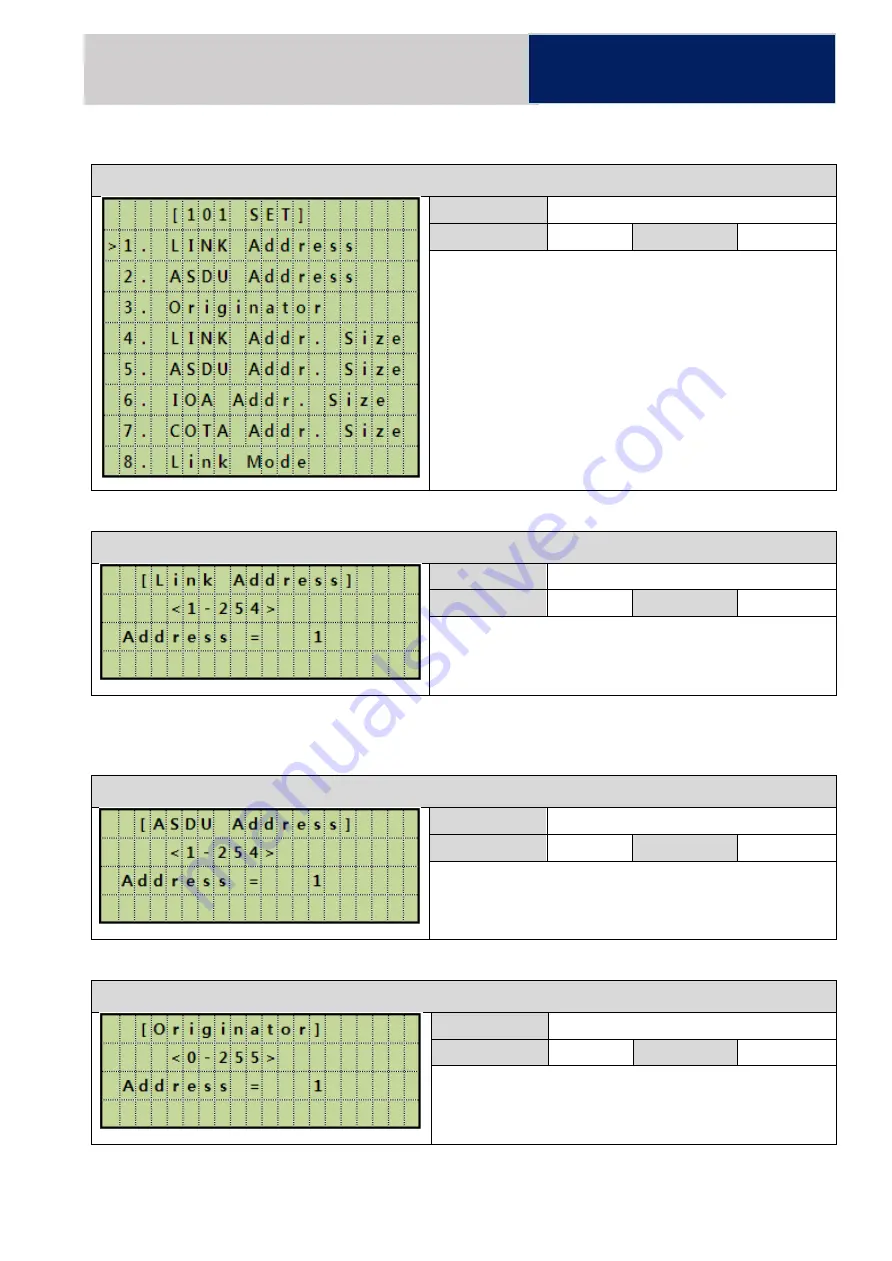
IEC 101 Parameter Setting
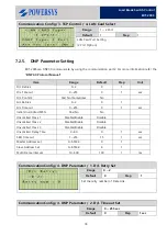
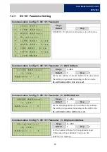
Communication Config/ 5. IEC 101 Parameter
Range
Default
Step
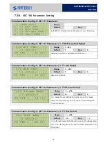
IEC60870-5-101 protocol setting menu is as following.
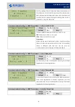
Communication Config/ 5. IEC 101 Parameter / 1. LINK Address
Range
1 ~254
Default
1
Step
1
Set the link address of the IEC 60870-5-101 slave station
The setting range varies depending on the Link size.
Re-confirmation after Link size is set.
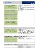
Communication Config/ 5. IEC 101 Parameter / 2. ASDU Address
Range
1 ~ 254
Default
1
Step
1
Set the ASDU(Application Service Data Units) Address.
The setting range varies depending on the ASDU size.
Re-confirmation after ASDU size is set.
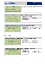
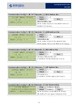
Communication Config/ 5. IEC 101 Parameter / 3. Originator Address
Range
0 ~ 254
Default
1
Step
1
Set the number of bytes for the application layer
“
Information Object Address
”
field in an IEC
60870-5-101 message.
Summary of Contents for ERT-200S
Page 1: ...Feeder Remote terminal Unit ERT 200S Manual www powersys kr...
Page 13: ...13 Load Break Switch Control ERT 200S 2 5 Function BlockDiagram...
Page 38: ...38 Load Break Switch Control ERT 200S 5 3 3 Menu structure tree Figure Menu Tree Structure...
Page 42: ...42 Load Break Switch Control ERT 200S...
Page 96: ...Appendix 1 Drawings 1 Enclosure Control Cabinet...

