- 18 -
4. Installation Instructions
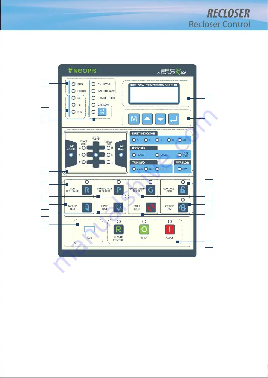
4.1. Front Panel and names of each part
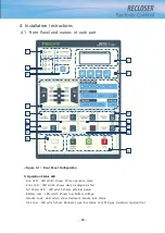
<Figure 4-1> Front Panel Configuration
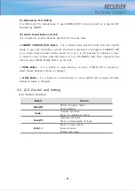
1) Operation Status LED
- Run LED : LED which shows CPU’s operation state
- Error LED : LED which shows device’s diagnosis fail
- AC Power LED : LED which shows external power
- Battery Low : LED which shows low battery voltage
- Handle Lock : LED which show Recloser’s handle lock status
- Gas Low : LED which show Recloser’s gas low status only SF6 gas insulation type(option)
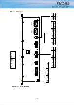
3
2
5
6
8
12
7
15
10
9
13
16
1
11
14
4
Summary of Contents for RECLOSER
Page 1: ...User Manual Document Version 1 5 Feb 28 2019 http powersys kr http www powersys kr...
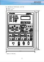
Page 14: ...8 3 5 Mechanical Performance and Size Weight 3 5 kg FRONT VIEW Figure 3 1 Front View...
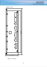
Page 15: ...9 SIDE VIEW 343 00 310 00 91 00 Figure 3 2 Side View...
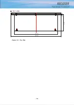
Page 16: ...10 TOP VIEW 84 0 260 0 225 0 1 0 0t Figure 3 3 Top View...
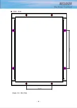
Page 17: ...11 REAR VIEW 180 0 120 0 Figure 3 4 Rear View...
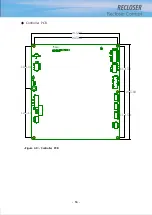
Page 22: ...16 Controller PCB 215 00 103 90 121 10 112 50 112 50 235 00 205 00 Figure 3 8 Controller PCB...
Page 69: ...63...
Page 71: ...65 Example configuration file...
Page 73: ...67 2 TC Curve 1 4 100 101 10 1 100 101 102 Time sec Current In Multiplies of Setting 1 2 3 4...
Page 74: ...68 3 TC Curve 5 8 100 101 10 1 100 101 102 Time sec Current In Multiplies of Setting 5 6 7 8...
Page 77: ...71 6 TC Curve A D 100 101 10 1 100 101 102 Time sec Current In Multiplies of Setting A B C D...
Page 78: ...72 7 TC Curve E M 100 101 10 1 100 101 102 Time sec Current In Multiplies of Setting E K L M...
Page 79: ...73 8 TC Curve N T 100 101 10 1 100 101 102 Time sec Current In Multiplies of Setting N P R T...
Page 80: ...74 9 TC Curve V Z 100 101 10 1 100 101 102 Time sec Current In Multiplies of Setting V W Y Z...

