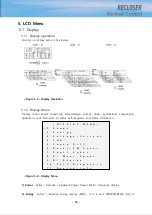
- 30 -
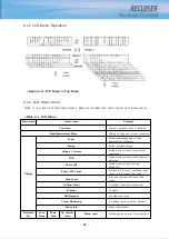
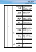
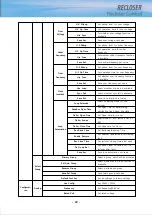
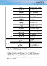
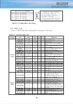
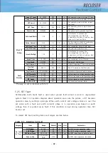
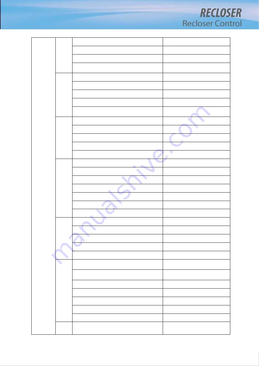
Check
Auto
batt
Check Day
Set auto checking day for battery
Check Hour
Set auto checking hour for battery
Check Min
Set auto checking minute for battery
Save Config
Save config set value for battery auto
checking
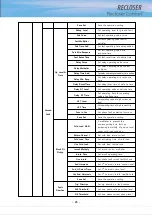
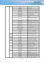
Check
Auto
batt(op
tion)
Auto-Check Day
Set auto checking day for battery
Detect Batt-Low
Set voltage level for battery low
Cut-Off Voltage
Set voltage level for battery cutoff
Cut-Off Delay
Set delay time for battery cutoff
Save Config
Save config set value for battery auto
checking
V/I
Unbala
nce
V Unbalance
Set unbalance level for voltage
V Unbalance Time
Set unbalance time for voltage
I Unbalance
Set unbalance level for current
I Unbalance Time
Set unbalance time for current
Save Config
Save V/I unbalance set value
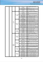
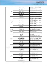
Sag/Sw
ell
Sag Level
Set pickup level for sag
Sag Time
Set operation time for sag
Swell Level
Set pickup level for swell
Swell Time
Set operation time for swell
Interrupt Level
Set pickup level for interruption
Interrupt Time
Set operation time for interruption
Save Config
Save config set value for Sag/Swell
THD
Alarm
V THD Alarm Level
Set alarm level for voltage THD
V THD Alarm Time
Set alarm time for voltage THD
I THD Alarm Level
Set alarm level for current THD
I THD Alarm Time
Set alarm time for current THD
Save Config
Save config set value for THD alarm
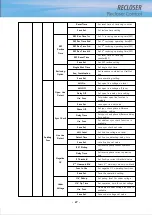
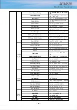
VI
Wear
Max Op Count
Set the type of the VI used in the
recloser
Alarm Level
Set alarm level for residual contact
wear
Duty Factor A
Set duty factor for A phase’s VI
Duty Factor B
Set duty factor for B phase’s VI
Duty Factor C
Set duty factor for C phase’s VI
Save Config
Save config set value for VI Wear
Clear Wear Info
Clear wear information
Analog
High
Phase Current
Set phase current level for Analog
High Alarm function
Summary of Contents for RECLOSER
Page 1: ...User Manual Document Version 1 5 Feb 28 2019 http powersys kr http www powersys kr...
Page 14: ...8 3 5 Mechanical Performance and Size Weight 3 5 kg FRONT VIEW Figure 3 1 Front View...
Page 15: ...9 SIDE VIEW 343 00 310 00 91 00 Figure 3 2 Side View...
Page 16: ...10 TOP VIEW 84 0 260 0 225 0 1 0 0t Figure 3 3 Top View...
Page 17: ...11 REAR VIEW 180 0 120 0 Figure 3 4 Rear View...
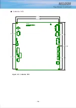
Page 22: ...16 Controller PCB 215 00 103 90 121 10 112 50 112 50 235 00 205 00 Figure 3 8 Controller PCB...
Page 69: ...63...
Page 71: ...65 Example configuration file...
Page 73: ...67 2 TC Curve 1 4 100 101 10 1 100 101 102 Time sec Current In Multiplies of Setting 1 2 3 4...
Page 74: ...68 3 TC Curve 5 8 100 101 10 1 100 101 102 Time sec Current In Multiplies of Setting 5 6 7 8...
Page 77: ...71 6 TC Curve A D 100 101 10 1 100 101 102 Time sec Current In Multiplies of Setting A B C D...
Page 78: ...72 7 TC Curve E M 100 101 10 1 100 101 102 Time sec Current In Multiplies of Setting E K L M...
Page 79: ...73 8 TC Curve N T 100 101 10 1 100 101 102 Time sec Current In Multiplies of Setting N P R T...
Page 80: ...74 9 TC Curve V Z 100 101 10 1 100 101 102 Time sec Current In Multiplies of Setting V W Y Z...

