- 46 -
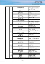
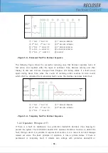
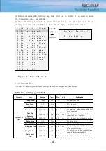
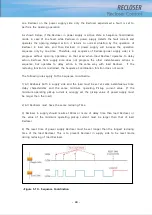
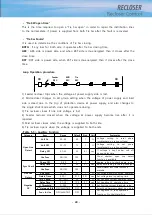
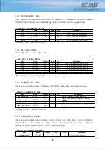
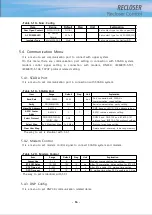
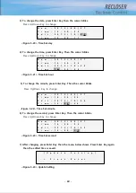
If the voltages of Source and Load sides are out of phase setting range, Sync Fail occurs
and then sync LED operates.
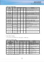
3) Live Line Detect
: Setting for monitoring live line
Any of the phase from 3 phase voltage from source side is over Voltage On, Hot Line
Source LED light will be on and determines the Source side as Hot Line.
Load side also operates in the same principle.
4) Negative OC
: Protection function for reverse phase current.
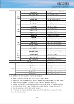
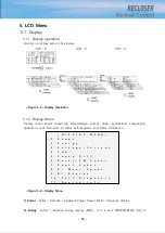
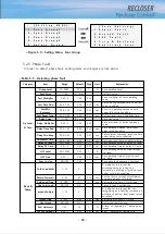
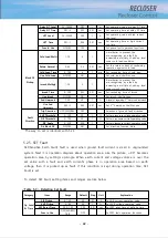
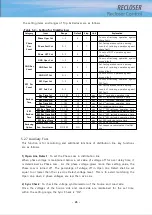
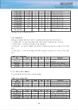
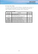
The setting items and ranges of Auxiliary Function are as follows.
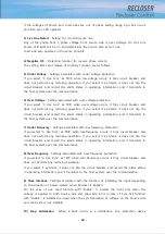
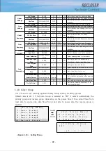
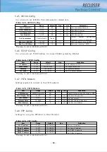
5) Under Voltage
: Settings associated with under voltage protection
If you select “3. Use Func” as TRIP, when low-voltage occurs, it trips circuit breaker, and
does not perform any reclosing operation. If you select it as Alarm, it does not trip the
circuit breaker, and record the alarm status in operating information, and it transmits to
the host system over the communication.
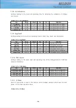
6) Over Voltage
: Setting associated with over voltage protection
If you select “3. Use Func” as TRIP, when over-voltage occurs, it trips circuit breaker, and
does not perform any reclosing operation. If you select it as Alarm, it does not trip the
circuit breaker, and record the alarm status in operating information, and it transmits to
the host system over the communication.
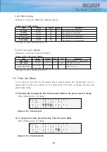
7) Under Frequency
: Settings associated with low-frequency protection
If you select “3. Use Func” as TRIP, when low-frequency occurs, it trips circuit breaker, and
does not perform any reclosing operation. If you select it as Alarm, it does not trip the
circuit breaker, and record the alarm status in operating information, and it transmits to
the host system over the communication.
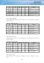
8) Over Frequency
: Settings associated with over-frequency protection
If you select “3. Use Func” as TRIP, when over-frequency occurs, it trips circuit breaker, and
does not perform any reclosing operation.
If you select it as Alarm, it does not trip the circuit breaker, and record the alarm status
in operating information, and it transmits to the host system over the communication.
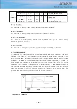
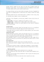
9) Close Interlock
: Settings associated with the function of inhibiting the input depending
on the situation of power system, when Recloser is applied.
For the case of Live Load function with “Enable”, it inhibits the input only when the
voltage is applied to both Source side and Load side. And, in case of Sync Fail function
with “Enable”, it inhibits the input when the synchronization of voltage on the Source side
and Load side is not suitable.
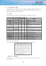
10) Loop Automation
: When a fault occurs in a distribution line, protection device
Summary of Contents for RECLOSER
Page 1: ...User Manual Document Version 1 5 Feb 28 2019 http powersys kr http www powersys kr...
Page 14: ...8 3 5 Mechanical Performance and Size Weight 3 5 kg FRONT VIEW Figure 3 1 Front View...
Page 15: ...9 SIDE VIEW 343 00 310 00 91 00 Figure 3 2 Side View...
Page 16: ...10 TOP VIEW 84 0 260 0 225 0 1 0 0t Figure 3 3 Top View...
Page 17: ...11 REAR VIEW 180 0 120 0 Figure 3 4 Rear View...
Page 22: ...16 Controller PCB 215 00 103 90 121 10 112 50 112 50 235 00 205 00 Figure 3 8 Controller PCB...
Page 69: ...63...
Page 71: ...65 Example configuration file...
Page 73: ...67 2 TC Curve 1 4 100 101 10 1 100 101 102 Time sec Current In Multiplies of Setting 1 2 3 4...
Page 74: ...68 3 TC Curve 5 8 100 101 10 1 100 101 102 Time sec Current In Multiplies of Setting 5 6 7 8...
Page 77: ...71 6 TC Curve A D 100 101 10 1 100 101 102 Time sec Current In Multiplies of Setting A B C D...
Page 78: ...72 7 TC Curve E M 100 101 10 1 100 101 102 Time sec Current In Multiplies of Setting E K L M...
Page 79: ...73 8 TC Curve N T 100 101 10 1 100 101 102 Time sec Current In Multiplies of Setting N P R T...
Page 80: ...74 9 TC Curve V Z 100 101 10 1 100 101 102 Time sec Current In Multiplies of Setting V W Y Z...

