- 52 -
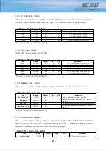
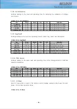
5.3.2. DI Debounce Time
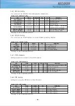
It is a menu to set debounce time to prevent DI Chattering. It is available to set on each channel.
During set time, DI status value should be kept to be considered with the changed value.
<Table 5-7> DI Debounce Setting
Item
Range
Default
Step
Unit
Explanation
DI_1
1~500
10
1
ms
DI 1’s debounce time setting
DI_2
1~500
10
1
ms
DI 2’s debounce time setting
DI_3
1~500
10
1
ms
DI 3’s debounce time setting
...
...
...
...
...
...
DI_10
1~500
10
1
ms
DI 10’s debounce time setting
The way to set is identical with 5.3.1
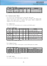
5.3.3. DO Pulse Width
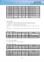
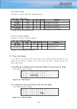
It sets DO1~6’s on pulse output time.
<Tabel 5-8> DI Pulse Setting
The way to set is identical with 5.3.1
5.3.4. Backup Set / Clear
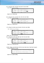
It is a menu operating switch operation count, Event data clear, Fault data and clear.
<Table 5-9> Backup Set / Clear
The way to set is identical with 5.3.1
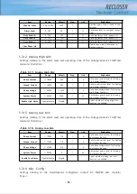
5.3.5. Analog Gain Adjust
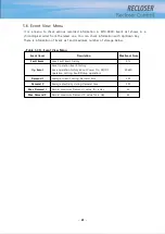
It is a menu to adjust analog voltage / current volume gain. EPIC-R300 is set in calibration
about voltage / current signal input from factory. However if measuring value is different
because of external sensor’s error, use the menu to adjust.
<Table 5-10> Analog Gain Adjust
Item
Range
Default
Step
Unit
Explanation
DO_1
10~2000
500
10
ms
DO 1’s pulse width time setting
DO_2
10~2000
500
10
ms
DO 2’s pulse width time setting
DO_3
10~2000
500
10
ms
DO 3’s pulse width time setting
DO_4
10~2000
500
10
ms
DO 4’s pulse width time setting
DO_5
10~2000
500
10
ms
DO 5’s pulse width time setting
DO_6
10~2000
500
10
ms
DO 6’s pulse width time setting
Item
Range
Default
Step
Unit
Explanation
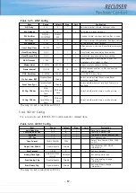
Set Switch Cnt
0~65535
0
1
Set the number of switch operation
Clear Event
NO/YES
NO
Delete saved event information in backup
memory
Clear Fault
NO/YES
NO
Delete save fault information in backup memory
Clear Oper Count
NO/YES
No
Delete save operation information in backup
memory
Item
Range
Default
Step
Unit
Explanation
Ia Gain Adjust
10~2000
0
1
A
Adjust current Ia’s gain
Summary of Contents for RECLOSER
Page 1: ...User Manual Document Version 1 5 Feb 28 2019 http powersys kr http www powersys kr...
Page 14: ...8 3 5 Mechanical Performance and Size Weight 3 5 kg FRONT VIEW Figure 3 1 Front View...
Page 15: ...9 SIDE VIEW 343 00 310 00 91 00 Figure 3 2 Side View...
Page 16: ...10 TOP VIEW 84 0 260 0 225 0 1 0 0t Figure 3 3 Top View...
Page 17: ...11 REAR VIEW 180 0 120 0 Figure 3 4 Rear View...
Page 22: ...16 Controller PCB 215 00 103 90 121 10 112 50 112 50 235 00 205 00 Figure 3 8 Controller PCB...
Page 69: ...63...
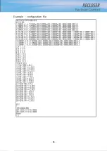
Page 71: ...65 Example configuration file...
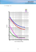
Page 73: ...67 2 TC Curve 1 4 100 101 10 1 100 101 102 Time sec Current In Multiplies of Setting 1 2 3 4...
Page 74: ...68 3 TC Curve 5 8 100 101 10 1 100 101 102 Time sec Current In Multiplies of Setting 5 6 7 8...
Page 77: ...71 6 TC Curve A D 100 101 10 1 100 101 102 Time sec Current In Multiplies of Setting A B C D...
Page 78: ...72 7 TC Curve E M 100 101 10 1 100 101 102 Time sec Current In Multiplies of Setting E K L M...
Page 79: ...73 8 TC Curve N T 100 101 10 1 100 101 102 Time sec Current In Multiplies of Setting N P R T...
Page 80: ...74 9 TC Curve V Z 100 101 10 1 100 101 102 Time sec Current In Multiplies of Setting V W Y Z...

