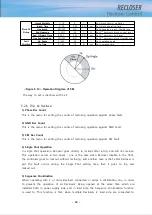
- 56 -
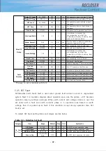
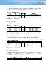
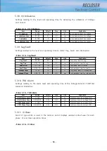
<Table 5-19> Misc. Config
Item
Range
Default
Step
Unit
Explanation
Door Open Contact
N.O(A)/N.C(B)
N.O(A)
Set contact type for door open(DI6)
AC POWER LED
AC Fail/AC
Normal
AC Fail
Set contact type for AC POWER(DI3)
Insulator Type
Mold/SF6-GAS
Mold
Set contact type for Gaslow(DI7)
5.4. Communication Menu
It is a menu to set communication port to connect with upper system.
On this menu there are communication port setting in connection with SCADA system,
modem control signal setting in connection with modem, DNP3.0, IEC60870-5-101,
IEC60870-5-104, TCP/IP protocol related setting.
5.4.1. SCADA Port
It is a menu to set communication port in connection with SCADA system.
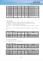
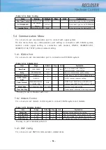
<Table 5-19> SCADA Port
The way to set is identical with 5.3.1
5.4.2. Modem Control
It is a menu to set modem control signal to connect SCADA system and modem.
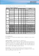
<Table 5-20> Modem Control
The way to set is identical with 5.3.1
5.4.3. DNP Config
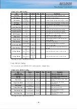
It is a menu to set DNP3.0 communication related items.
Item
Range
Default
Step
Unit
Explanation
Baud Rate
1200~38400
9600
bps
Port connected with SCADA’s
communication speed setting
Parity
NO/EVEN/ODD
NO
Serial communication parity setting
Slave/DL Address
0~65534
2
1
DNP slave or IEC-101 D/L address setting
ASDU Comm
Addr
0~65534
2
1
ASDU common address setting
Select Protocol
DNP/DNP-TCP/IEC-
101/IEC-104/
DNP
DNP3.0 and DNP-TCP and IEC870-5-101
protocol and IEC870-5-104 protocol setting
Select Map
Full Map/User Map
Full Map
Protocol map type setting
Clear User Map
Delete saved user map in backup memory
Item
Range
Default
Step
Unit
Explanation
Comm Line
2 / 4
4
Modem communication line setting
RTS Off Delay
10~500
100
10
ms
After TX completion, delay setting for RTS Off
CTS Time out
0~255
3
1
s
After RTS enable, CTS waiting time setting
DCD Time out
0.1~30
10
0.1
s
TX waiting time when DCD is enable on 2 Line
Summary of Contents for RECLOSER
Page 1: ...User Manual Document Version 1 5 Feb 28 2019 http powersys kr http www powersys kr...
Page 14: ...8 3 5 Mechanical Performance and Size Weight 3 5 kg FRONT VIEW Figure 3 1 Front View...
Page 15: ...9 SIDE VIEW 343 00 310 00 91 00 Figure 3 2 Side View...
Page 16: ...10 TOP VIEW 84 0 260 0 225 0 1 0 0t Figure 3 3 Top View...
Page 17: ...11 REAR VIEW 180 0 120 0 Figure 3 4 Rear View...
Page 22: ...16 Controller PCB 215 00 103 90 121 10 112 50 112 50 235 00 205 00 Figure 3 8 Controller PCB...
Page 69: ...63...
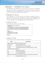
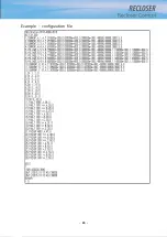
Page 71: ...65 Example configuration file...
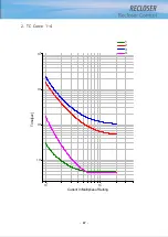
Page 73: ...67 2 TC Curve 1 4 100 101 10 1 100 101 102 Time sec Current In Multiplies of Setting 1 2 3 4...
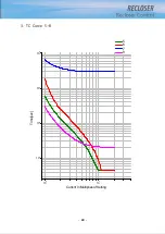
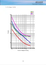
Page 74: ...68 3 TC Curve 5 8 100 101 10 1 100 101 102 Time sec Current In Multiplies of Setting 5 6 7 8...
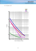
Page 77: ...71 6 TC Curve A D 100 101 10 1 100 101 102 Time sec Current In Multiplies of Setting A B C D...
Page 78: ...72 7 TC Curve E M 100 101 10 1 100 101 102 Time sec Current In Multiplies of Setting E K L M...
Page 79: ...73 8 TC Curve N T 100 101 10 1 100 101 102 Time sec Current In Multiplies of Setting N P R T...
Page 80: ...74 9 TC Curve V Z 100 101 10 1 100 101 102 Time sec Current In Multiplies of Setting V W Y Z...

