- 58 -
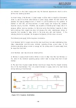
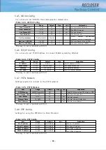
5.4.5. IEC104 Config
It is a menu to set IEC870-5-104 communication related item.
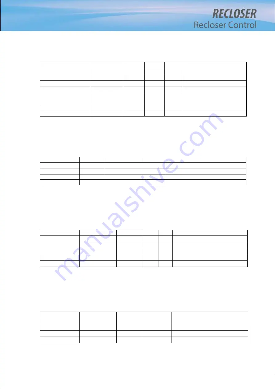
<Table 5-23> IEC104 Config
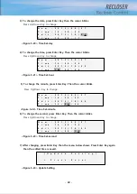
The way to set is identical with 5.3.1
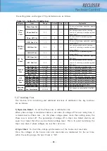
5.4.6. TCP/IP Config
It is a menu to set TCP/IP address to connect SCADA system by Ethernet.
<Table 5-24> TCP/IP Config
The way to set is identical with 5.3.1
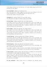
5.4.7. PSTN Modem
Settings required to connect to the PSTN network.
<Table 5-25> PSTN Modem
The way to set is identical with 5.3.1
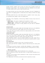
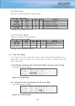
5.4.8. PPP Config
Settings for using the PPP(Point to Point Protocol).
<Table 5-26> PPP Config
The way to set is identical with 5.3.1
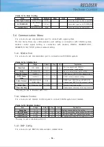
Item
Range
Default
Step
Explanation
IP Address
0~255
0.0.0.0
1
Set IP address of FTU
Subnet Mask
0~255
255.255.255.0
1
Set subnet mask bits
Gateway
0~255
192.168.0.0
1
Set gateway address
NTP Server
0~255
192.168.0.0
1
Set NTP Server address
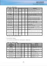
Item
Range
Default
Step
Unit
Explanation
Conn Timeout(t0)
1~255
30
1
sec
Set connection timeout
APDU Timeout(t1)
1~255
15
1
sec
Set APDU timeout
Ack Timeout(t2)
1~255
10
1
sec
Set ack timeout
Test Period(t3)
1~255
20
1
sec
Set time period
Xmt Spontaneous
Disable/Enable
Disable
Select
whether
spontaneous
response function is available
Max Xmt I-APDU(k)
1~32767
15
1
Set max transmitting I-APDU
Max Rcv I-APDU(w)
1~32767
10
1
Set max receiving I-APDU
Item
Range
Default
Step
Unit
Explanation
PSTN Modem
NO/PPP/Dialup/SMS
NO
Select PSTN mode type,PPP, dialup or SMS
Auto Hangup Time
0~255
30
1
sec
Set Auto hangup time
Dial Timeout
10~255
90
1
sec
Set dial timeout
Attempt Delay
10~3600
60
1
sec
Set dial attempt delay time
Max Attempts
1~5
3
1
sec
Set dial max attempt
Item
Range
Default
Step
Explanation
Our IP address
0~255
192.168.0.0
1
Set our IP address
Their IP address
0~255
192.168.0.0
1
Set their IP address
DNS1 IP address
0~255
192.168.0.0
1
Set DNS1 IP address
DNS2 IP address
0~255
192.168.0.0
1
Set DNS2 IP address
Summary of Contents for RECLOSER
Page 1: ...User Manual Document Version 1 5 Feb 28 2019 http powersys kr http www powersys kr...
Page 14: ...8 3 5 Mechanical Performance and Size Weight 3 5 kg FRONT VIEW Figure 3 1 Front View...
Page 15: ...9 SIDE VIEW 343 00 310 00 91 00 Figure 3 2 Side View...
Page 16: ...10 TOP VIEW 84 0 260 0 225 0 1 0 0t Figure 3 3 Top View...
Page 17: ...11 REAR VIEW 180 0 120 0 Figure 3 4 Rear View...
Page 22: ...16 Controller PCB 215 00 103 90 121 10 112 50 112 50 235 00 205 00 Figure 3 8 Controller PCB...
Page 69: ...63...
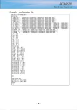
Page 71: ...65 Example configuration file...
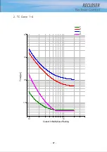
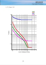
Page 73: ...67 2 TC Curve 1 4 100 101 10 1 100 101 102 Time sec Current In Multiplies of Setting 1 2 3 4...
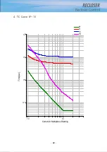
Page 74: ...68 3 TC Curve 5 8 100 101 10 1 100 101 102 Time sec Current In Multiplies of Setting 5 6 7 8...
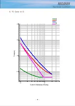
Page 77: ...71 6 TC Curve A D 100 101 10 1 100 101 102 Time sec Current In Multiplies of Setting A B C D...
Page 78: ...72 7 TC Curve E M 100 101 10 1 100 101 102 Time sec Current In Multiplies of Setting E K L M...
Page 79: ...73 8 TC Curve N T 100 101 10 1 100 101 102 Time sec Current In Multiplies of Setting N P R T...
Page 80: ...74 9 TC Curve V Z 100 101 10 1 100 101 102 Time sec Current In Multiplies of Setting V W Y Z...

