UNPACKING
Refer to Figure 1.
Check for shipping damage. Check immediately whether
all parts and accessories are included.
The sander comes assembled as one unit. Additional
parts which need to be fastened to sander, should be
located and accounted for before assembling.
ITEM DESCRIPTION QUANTITY
A
Dust Chute
1
B
Screw M4×12 (dust chute assembly)
4
C
Spring washer (dust chute assembly) 4
D
Flat washer (dust chute assembly)
4
E
Sanding Disc Table
1
F
Locking Levers (sanding disc table)
2
G
Belt Guard Locking Knob
1
H
Upper Belt Guard
1
I
Lower Belt Guard
1
J
Sanding Belt Table
1
K
Locking Lever (Sanding Belt Table)
1
Figure 1
I
F
A
E
G
H
J
K
B
C
D
ASSEMBLY
2
WARNING
Do not use the machine until it is completely assembled
and you have read and understood the entire operating
manual.
TOOLS NEEDED
The following tools (not included) are needed to assemble
and adjust the belt/disc sander:
• Combination square
• Phillips screwdriver
• Standard screwdriver
• 4 mm Hex Wrench
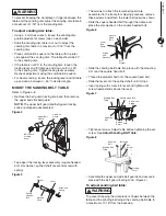
MOUNT THE DUST CHUTE
Refer to Figure 2
• Secure the dust chute to the sander with screws, flat
washers and spring washers supplied. Ensure the dust
chute opening faces the rear of the unit.
Figure 2
Dust Chute
Screws
Flat Washers
Spring Washers
MOUNT THE SANDING DISC TABLE
Refer to Figure 3
• Align the sanding disc table to the guard and slide the
hinge pins into the slots on the sanding disc guard.
Secure in place with locking levers (one on each side).
Figure 3
Sanding
Disc
Guard
Slot
Hole for
Locking
Lever
Hinge Pins
Locking
Lever
Sanding Disc Guard
Adjustment Screw
Sanding
Disc
Sanding
Disc
Table
2
ASSEMBLY


