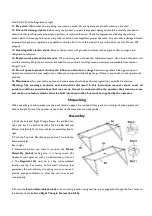
5. Carefully place each
Solar Panel (1)
on the front of the
Frame Assembly (6a-6d)
so that the bottom of each panel fits
into the slot on the bottom of the
Frame Assembly (6a-6d)
.
6. Lock the two eye hooks on the back-center frame into the two protruding bolts on the
Top Link Bar (6d)
.
Caution:
If the unit is to be mounted on a rooftop, always be especially careful when climbing ladders and walking on sloped
roofs. Additional hardware may have to be purchased if permanently mounting the Solar panels on a rooftop.
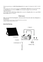
7. Connect the two ring connectors at the end of the lead wires coming from the
Solar Panels (1)
to the Solar Terminals
on the
Regulator (2)
. See
FIGURE 1
. Be sure to connect by matching polarities on the wires and the
Regulator (2)
. Black
(-) is negative and red (+) is positive. Then, connect the wire leads so that all of the
Solar Panels (1)
are connected to each
other and the
Regulator (2)
(again, making sure you are hooking up to the right polarity on the Regulator).
See
Hook-Up Diagram
, right.
Figure 1.
Operation
Note:
Performance of the Solar Panels will vary dependent on site location, angle of the panels in relation to the arc of the
sun, and available sunlight.
Recharging a Battery
(not included).
1. To recharge a 12 volt battery (not included), paying attention to the proper polarity (black (-) is negative and red (+) is
positive), connect the two ring terminals on the
Battery Clamp wire (3)
to the Battery Terminals on the back of the
Regulator (2)
. See
FIGURE 1
. Then, connect the black clamp to the black or negative (-) terminal on the battery (not
included). Finally, connect the red clamp to the red or positive (+) terminal on the battery. Always avoid accidental contact of
the red and black battery clamps to
each other.
Note:
Do not change the order explained in number 1 above or electric shock resulting in serious injury or death may occur.
2. Turn on the Regulator. See the On/Off switch in
FIGURE 2
.


