background image

16      INSTRUCTIONS PW220/PW230 

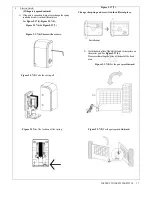
Figure 2.3.6 (4) 

Figure 2.3.6 (5) 

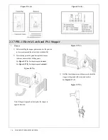
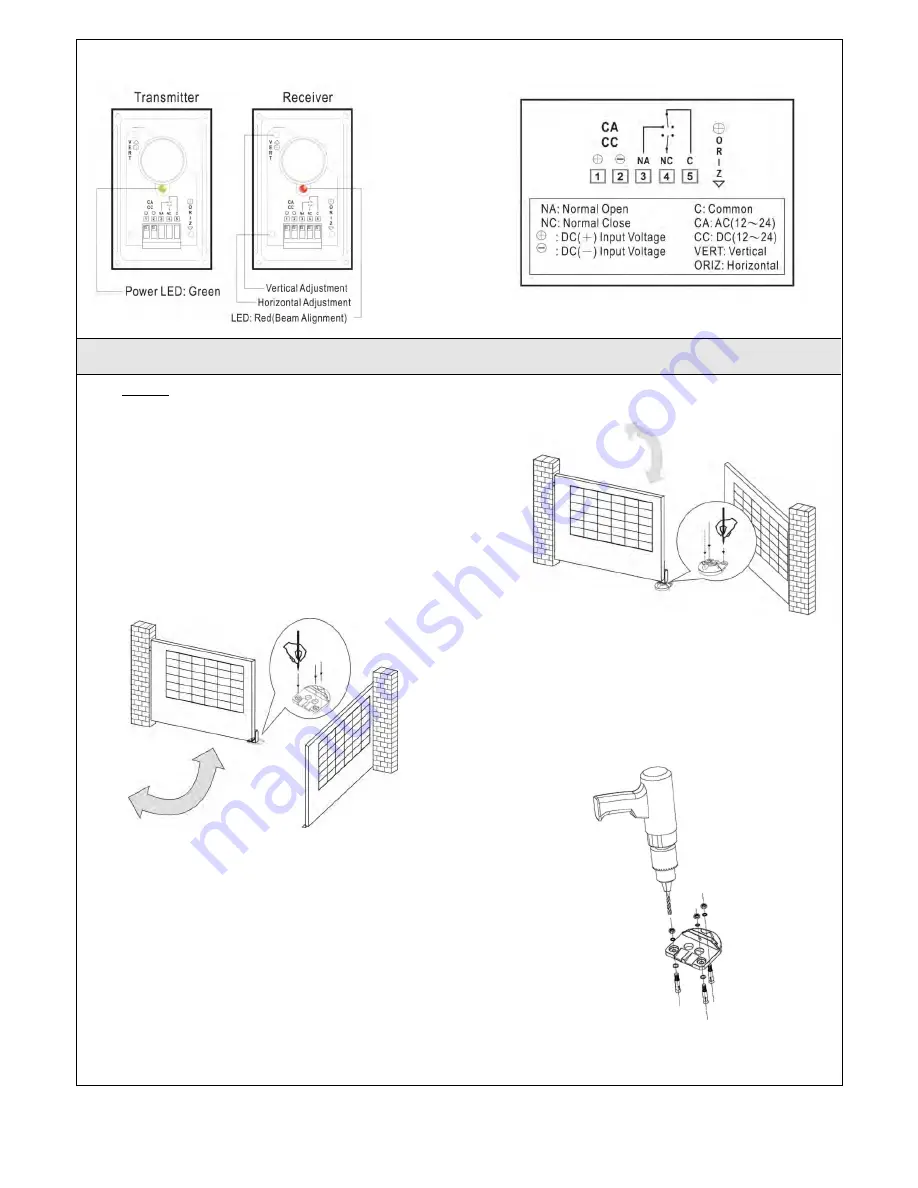
2.3.7 PEL-1 Electric Latch and PS-1 Stopper 

1.

Stopper:

1)

Before installing the stopper, please make sure the gates are 

in close positions and the surface to be installed is flat.

2)

Place the stopper on the ground using the bottom as 

reference, and mark the 3 drilling points.


See 

Figure 2.3.7 (1) 

For the gate opened 

inward.

See 

Figure 2.3.7 (2) 

For


the gate opened 

outward.

Figure 2.3.7(1) 

Note: If the gate is opened outward, place the stopper in 

opposite direction.   

Figure 2.3.7(2) 

3)

Drill the 3 marked points, and then securely attach the 

stopper to the ground with screws and washers.

See 

Figure 2.3.7 (3)

Figure 2.3.7(3) 

Summary of Contents for PW220

Page 1: ......

Page 2: ...ction 7 2 3 Installation 8 2 3 1 Preparation for Motor Installation 8 2 3 2 Installation of The Gear Motors 10 2 3 3 PKS 1 Key Selector 12 2 3 4 PPB 1 Push Button 13 2 3 5 PF 1 Flashing Light 14 2 3 6 PH 1 Photocells 15 2 3 7 PEL 1 Electric Latch and PS 1 Stopper 16 2 3 8 PC160 Control Box 18 3 Dip Switch Setting 21 3 1 Functional Switch and LED lights Introduction 22 3 2 Transmitter Memorizing an...

Page 3: ...s properly before installing the gate automated system and confirm the gates are appropriate for the application Do not let children operate or play with the gate automated system Do not cross the path of the gate automated system when operating Please keep all the control devices and any other pulse generator away from children to avoid the gate automated system being activated accidentally Do no...

Page 4: ...al installation describes some terms and accessories of a gate automation system Figure 1 1 3 Description of Devices PW220 PW230includestheaccessoriesshowninFigure2 Please check theaccessories thesameasthepackageprovided Attention Some accessories of PW220 PW230 are not included due to local regulations or customized order A 2 PW220 PW230 electromechanical gear motors with mounting brackets B 2 re...

Page 5: ...tteries PC160 provides the complete automation of the gear motors and other accessories ofPW220 PW230kit To connect separate terminals on the control panel and activate the gear motors and other accessories the installation manual has to be carefully read beforehand PW220 PW230 consists of a worm screw reduction gear and a 24V direct current motor The gear motor could be released manually by speci...

Page 6: ...e 9 PR 1 radio transmitter is used for the remote control of the gate movement To use the transmitter press and hold the button for 1 second There are two buttons on the transmitter for operating dual gate A or single gate B opening and closing PF 1 flashing light is controlled by PC160 control box and blinks when the gate is moving The flashing light stops blinking when the gates finish opening o...

Page 7: ...ht which can be opened up to 110 degrees primarily for residential use where the performance shall be influenced by the factors such as gate dimension weight and climate that the driven torque is necessarily to be adjusted properly 2 1 1 Tools in Installing Please make sure all tools and cables are ready and conform to the industrial safety standard before installation Please refer to Figure 11 Fi...

Page 8: ...ionally trained personnel is required in installation however the users are advised to read the installation manual carefully before going for it After getting to know all accessories and their positions suggest starting from cable conduit arrangement to prevent the cables from being broken or damaged 2 2 1 Notes for Power Connection 1 The installation of power supply cable to the motor should be ...

Page 9: ... automatic operation and force regulations 3 Make sure there is no serious friction existing in the opening or closing travel of the gate leaves 4 Make sure the gate is at horizontal level that the gate will not move aside at any position 5 Make sure the gate can bear the impact of the motor torque when it is installed on any hole of the bracket which the surface is sufficiently sturdy 6 Make sure...

Page 10: ... brackets and the gate Figure 15 aerial view 1 PW220 2 PW230 10 Using the leaf opening angle as criteria to make sure all criteria in Figure 17 can be met Figure 16 aerial view 1 PW220 2 PW230 Figure 17 1 PW220 2 PW230 Model PW220 Model PW230 11 C value is 139mm 12 D can be measured from the gate easily ...

Page 11: ...btain the optimal supporting from the rear plate please assemble two post brackets and one rear metal plate according to Figure 18 Figure 18 5 Loosen the two screws and remove the back cover of the motor as shown in Figure19 Figure 19 6 Place the leaves in the closed position 7 Refer to the distance of B in Figure 17 place the rear plate in the correct position on the mounting surface Inspect if t...

Page 12: ...he nut tightly and loosen it for half round for motor supporting in rotating 15 Fasten the motor front end to the front plate with the bolt A and nut B tightly Fully tighten the screw Figure 26 1 PW220 2 PW230 16 Use appropriate release key to releasethe gear motor 17 Try to push the released gate and make sure the motor can be manually moved easily 18 Make sure the motor front plate can be fasten...

Page 13: ... end See Figure 31 Figure 31 2 3 3 PKS 1 Key Selector 1 PKS 1 key selector is installed outside and close to the gate at the height of about 100cm so that it could be used by most people Decide the installation position of PKS 1 first See Figure 2 3 3 1 Figure 2 3 3 1 2 Remove the round cover A by prizing it out with the tip of a screwdriver See Figure 2 3 3 2 Figure 2 3 3 2 3 Unscrew the two scre...

Page 14: ...ly Figure 2 3 3 6 8 Turn the key and insert the shell on the bottom Turn the key back to the center position and the shell will be fixed to the bottom 9 Tighten the lock body with the two screws and insert the round cover by pressing it to attach to the whole unit 2 3 4 PPB 1 Push Button 1 PPB 1 push button is installed indoors at the height of about 100cm so that it could be used by most people 2...

Page 15: ...nd cover by pressing it to attach to the whole unit 2 3 5 PF 1 Flashing Light 1 Decide the installation position of the flashing light The flashing light has to be installed near the gate and easy to be seen by users and passersby The flashing light can be installed horizontally or vertically See Figure 2 3 5 1 Figure 2 3 5 1 2 Unscrew the four screws on the light base and separate the base with t...

Page 16: ...r and replace the bulb set with a new one 4 Tighten the three screws A B C of the flashing light cover Figure 2 3 5 7 2 3 6 PH 1 Photocells 1 Decide the installation position of the photocells See Figure 2 3 6 1 Figure 2 3 6 1 2 Unscrew the screws and secure the photocells on the post A B or C Figure 2 3 6 2 Figure 2 3 6 3 3 Wiring connection TX Connect terminals 1 and 2 on the transmitter with th...

Page 17: ...flat 2 Place the stopper on the ground using the bottom as reference and mark the 3 drilling points See Figure 2 3 7 1 For the gate opened inward See Figure 2 3 7 2 For the gate opened outward Figure 2 3 7 1 Note Ifthe gate is opened outward place the stopper in opposite direction Figure 2 3 7 2 3 Drill the 3 marked points andthen securelyattach the stopper tothe ground with screws and washers See...

Page 18: ...7 7 Figure 2 3 7 4 Unscrew the screws Figure 2 3 7 5 Take the casing off Figure 2 3 7 6 The location of the spring Figure 2 3 7 7 Change the spring and screw it in the different place Installation 2 Weld the back plate ofthe electric latch tothesurface on the master gate SeeFigure 2 3 7 8 Please avoid melting the wires bythe heat ofthe fixed plate Figure 2 3 7 8 For the gate opened inward Figure 2...

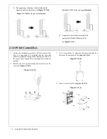
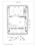
Page 19: ...2 3 8 PC160 Control Box 1 Decide the installation position of PC160 control box first it is suggested to be installed near the gate and should be protected from possible damage Be aware of the motor cable length before deciding the installation position 2 Remove the cover by unscrewing the four screws on the cover See Figure 2 3 8 1 Figure 2 3 8 1 3 Use a screwdriver to puncture the holes beneath ...

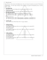
Page 20: ...ire White to the terminals M2 and Yellow to the M2 Notes For gates opened outward M1 Connect the motor wire Yellow to the terminals M1 and White to the terminals M1 M2 Connect the motor wire Yellow to the terminals M2 and White to the terminals M2 4 PH 1 Photocells Please remove the cover of JP1 and connect the wires to proper terminals 5 PKS 1 Key Selector For Single leaf operation Refer to Figur...

Page 21: ...20 INSTRUCTIONS PW220 PW230 Figure 2 3 8 4 ...

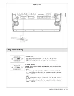
Page 22: ... moves in the opening phase the photo sensor can be selected as active or inactive ON In the opening phase the gate will stop when the photo sensor is activated In the closing phase the gate will stop and open to the end when the photo sensor is activated OFF In the opening phase the gate will not stop when the photo sensor is activated In the closing phase the gate will stop and open to the end w...

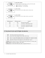
Page 23: ...ng time 12 seconds 3 1 Functional Switch and LED lights Introduction SW2 The button of transmitter memorizing and erasing VR1 Over current limit can be adjusted from min 0 8Amp to Max 4 2 Amp VR2 The over current sensitivity of Master Gate M1 could be adjusted from 1 8 second to 3 8 second VR3 The over current sensitivity of Master Gate M1 could be adjusted from 1 8 second to 3 8 second VR4 Close ...

Page 24: ... mode for gate operation systems Step1 Connect the wires of two motors with terminal M1 M1 M2 M2 Step2 Connect 230VAC with terminal J1 and battery with J2 Setp3 In single leaf installation just connect the motor wires with terminal M1 M1 Step4 Press SW2 button for more than 1 second and the blue light on the receiver board is on Press the left button on the transmitter to memorize the transmitter ...

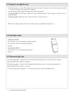
Page 25: ...in when an unpredictable interruption occurs 3 4 Gate Operation Figure 34 3 5 Gate moving Logic A In gate opening phase The gates stop if the transmitter push button key selector is activated and close when the transmitter push button key selector is reactivated B In gate closing phase The gates stop if the transmitter push button key selector is activated and open when the transmitter push button...

Page 26: ...ND terminal of the photocells on the PCB must be short circuited if no photocells installed The master gate closes to the end first and the slave gate stops the flashing light blinks fast for five seconds Cut off the AC input power and the output of the batteries Release the master gate and slave gate manually then open the master to the end and close the slave gate to the end by hand then power t...

Page 27: ...mm 106mm Weight 6 25kg 5 3 PC160 Control Box Application For PW220 PW230 power supply Main power supply 230Vac 110Vac 50Hz 60Hz Back up battery 2pcs of batteries for emergency operation 1 2A each Transformer 4 2A 24V Receiver board 433 92MHz 200 transmitters memory Installation Wall mounted vertically Operating Temperature 20 50 Dimension 275mm 195mm 102mm 5 4 PH 1 Photocells Detection type Throug...

Page 28: ...leaves movement Lamp 24Vdc Halogens bulb Operating Temperature 20 50 Installation horizontally or vertically installed Dimension 205mm 80mm 75mm 5 8 PR 1 Transmitter Application Radio transmitter for remote control of PW220 PW230 Frequency 433 92Mhz Coding Rolling code Buttons 2 for single gate or dual gate operation Power Supply 6V with two CR2016 type lithium batteries Operating Temperature 20 5...

Page 29: ...215 7550 1141 Budapest Fogarasi út 77 Tel 220 7940 220 7814 220 7959 216 7017 216 7018 Fax 218 5542 Mobil 30 940 1970 20 949 2688 E mail delton delton hu Web www delton hu www kaputnyitunk hu 220 8881 364 3428 Fax 220 7940 Mobil 30 531 5454 30 939 9989 ...

Reviews: