2
Read through these user instructions carefully before using the trolley. Improper operation may lead to hazardous situations!
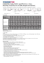
Geared trolley 0,5 - 5t
Geared trolley 10t
Push trolley 0,5 - 5t
Push trolley 10t
Technical data
Model
0,5t PGT
1t PGT
2t PGT
3t PGT
5t PGT
10t PGT
0,5t PPT
1t PPT
2t PPT
3t PPT
5t PPT
10t PPT
Capacity load t
0,5
1
2
3
5
10
0,5
1
2
3
5
10
Test load kg
750
1.500
3.000
4.500
7.500
15.000
750
1.500
3.000
4.500
7.500
15.000
Min. radius of curve m
0,8
1
1,1
1,3
1,4
2,0
0,8
1
1,1
1,3
1,4
2,0
Dimensions mm
A
a
382
398
420
456
474
402
267
289
318
345
364
380
b
508
516
526
556
566
504
393
107
424
445
457
482
B
224
270
300
356
405
485
224
270
300
356
405
490
C
159
190
218
262,5
292
395
159
190
218
262,5
292
395
D
-
-
-
-
-
72
-
-
-
-
-
72
H
57.5
(55.5)
67
(65)
74
(72)
87
(85)
95.5
(93.5)
189
57.5
(55.5)
67
(65)
74
(72)
87
(85)
95.5
(93.5)
189
S
30
35,5
36
38
41
45
30
35,5
36
38
41
45
E
27
29
43
(35.6)
46
56
-
27
29
43
(35.6)
46
56
-
G
18
(22)
22
(26)
28
(32)
34
(38)
39
(43)
112
18
(22)
22
(26)
28
(32)
34
(38)
39
(43)
112
F
1.5-3
2-3.5
1.5-3
2-3.5
I beam width range
M
a
50-180
66-188
88-200
100-205
114-212
124-203
50-180
66-188
88-200
100-205
114-212
124-203
b
176-305
184-305
194-305
200-305
208-305
124-305
176-305
184-305
194-305
200-305
208-305
124-305
Net weight kg
a
9
15
22
34
49
87
6
15
18
30
44
86
b
9,5
16
23,5
38
56
94
6,5
17
20
34
50
90
Gross weight kg
a
9,5
15,55
22,8
35
50,1
95
6,25
15,3
18,3
30,45
44,65
67
b
10
16,55
24,3
39
57,1
102
6,75
17,3
20,3
34,45
50,65
98
Safety factor: 4:1
Static test coefficient: WLL x 1,5
Generally according to EN 13157
1. Proper usage
Usage:
The trolleys can be used for I-beams with plane flanges (such as IPE, HEA or HEB types) or beams with sloping flanges (such as INP-beams).
The possible width ranges are shown in the data tables.
The trolley is a rolling and geared chassis for attaching to lifting gear for use inside.
It is not suitable for continuous operation.
It is not suitable for use in rooms where there is a potential risk of explosions.
It is not suitable for use in aggressive atmospheres.
The unit should be installed if possible in a covered room. If it is installed outdoors a roof is to be provided or the unit is to be covered.
Modifications to the lifting gear are only permitted with our express consent in writing.
Refer to the technical data and function description.
Safety instructions
Operation and servicing must be left strictly to: authorized, trained personnel.
• Only install the trolley on girders whose load capacity has been checked previously.
• Do not install the trolley on tapered girders.
• Stops on the ends of girders must not be moved or removed.
• Do not transport personnel or allow personnel to be located in the danger area.
• Do not allow the load to swing.
• Do not stand under a raised load.
• Never reach into moving parts.
• Defects are to be rectified immediately by trained personnel.
• Never leave the load off the ground without supervision.
• Loads may only be raised vertically. Do not raise loads at an angle.
• Do not use the trolley to pull items out of other items, release them or drag them sideways.
• The trolley may only be used to push or pull the load.
• Do not exceed the load capacity set out in the technical data.
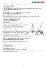
• Check the raceway width and adjust the distance between the chassis flanges using the figures in the table.
• The hand chain is only designed for moving the load attached to the lifting gear and must not be used for any other purpose.
• Never slew the load off the ground without supervision.
• High strength parts such as the chain, hook and gear parts must not come into contact with free hydrogen, acids, alkalis, vapour or very
aggressive cleaning products. They may become brittle and fracture.
• Conduct a risk analysis before use and verify EC conformity.
• Working temperature: -10°C to +50°C.
POWERTEX Trolley PGT-S1 and PPT-S1 0,5 – 10 ton
Mounting / Instruction for use (GB) (Original instructions)


