background image

Powertow 35/40/KeyEZ/Thundervolt

Powertow 35/40/KeyEZ/Thundervolt

USE 

EXTREME CAUTION

WHEN 

OPERATING ANY POWER EQUIPMENT!

1. Do not operate this machine until you have read and

understand all instructions for proper use.

2. Do not operate unit when not running smoothly.

3. Keep hands and feet out from under towing equipment.

4. Operate in well ventilated area.

5. Do not leave a running machine unattended.

6. Do not operate electric unit in wet conditions or if cords are frayed.

7. Do not start engine when unit is in gear.

8. Hangar storage area should include anchored chocks to

control inadvertent movement of planes into hangar walls.

9. Do not change gearing to increase speed.

10. Do not move planes up any inclines...flat surface only.

11. Do not attach any device to activate throttle when both hands - 

are not on throttle control.

12. Do not run engine without checking oil level.

13. Do not spill gasoline on hot engine.

14. Do not smoke when filling tank with gasoline.

15. Use caution when operating machine on icy / slippery surfaces.

16. Do not move planes in excess of speed that cannot be easily

stopped... there is no braking device on the unit.

17. Do routine maintenance to insure proper operation of unit.
18. Do not use unit if the Powertow engine is not running smoothly.

We hope you enjoy this Northwest Manufacturing product.

It was designed and built to give many years of reliable 

service with proper use and routine maintenance.

Summary of Contents for 35 EZ

Page 1: ...MODEL 35 40 EZ KEY EZ THUNDERVOLT Advanced Assembly OWNER S MANUAL REV 2 25 05 ...

Page 2: ...shipping damage to your unit Read this instruction manual thoroughly before attempting to move your aircraft Your unit will need Oil Gas before test running the unit Thank you for choosing a Powertow for your hangaring needs Customer Service is 1 with our company If you have any questions or comments on your unit please call us at 800 635 5565 P PO OW WE ER RT TO OW W ...

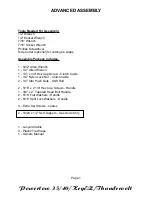
Page 3: ...aps Assembly Package Includes 1 5 32 Allen Wrench 1 1 4 Allen Wrench 1 1 4 x 3 4 Hex Cap Screw Clutch Cable 1 1 4 Nylon Lock Nut Clutch Cable 2 1 4 Star Push Nuts Shift Rod 2 5 16 x 2 1 4 Hex Cap Screws Handle 1 3 8 x 2 Tapered Head Bolt Handle 2 5 16 Flat Washers Handle 2 5 16 Split Lock Washers Handle 4 Extra Set Screws spares 2 10 24 x 1 2 Self Tappers Gas Units Only 1 Lanyard Cable 4 Plastic T...

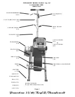
Page 4: ... 130 LANYARD CABLE 131 TRANSMISSION 300 CHAIN GUARD 251 DRIVE CHAIN 250 SPRING 260 ADAPTORS go here BEECH 701 STANDARD 702 SMALL 703 CESSNA 704 PIPER 705 SCOTT 706 FRAME EXTENSION PLANE WITH WHEELPANTS 700 GAS THROTTLE 303 SHIFT HANDLE 120 5 HP GAS ENGINE 350 OR 6 HP GAS ENGINE 400 TIRE ONLY 100 TIRE WHEEL AXLE SPROCKET 101 Page 2 CLUTCH ADJUSTOR CABLE 111 ...

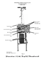
Page 5: ...ERTOW MODEL 35 40 EZ Key EZ GAS OR ELECTRIC PARTS LIST BELT GUIDES 201 GAS 202 ELECTRIC BELT 200 Replacement Belt Gates Green 6837 7 PULLEY 301 SNOWCHAINS FOR DRIVE WHEEL 910 Page 3 STAND LEGS 900 GAS ENGINE PULLEY 302 IDLER ARM 140 IDLER ARM PULLEY 141 PILLOW BLOCKS 102 ...

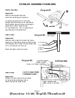
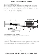
Page 6: ...aded hole Diagram 1 A B Clutch Cable Diagram 3 Secure the clutch cable at lower handle by removing the self tapper and re attach through the cable clamp CLUTCH CABLE CABLE CLAMP 10 24 X 1 2 SELF TAPPER BOTTOM VIEW LOWER HANDLE BELT GUIDES A B SIZE 2 5 16 X 2 CAPS CLUTCH CABLE RUNS UNDERNEATH BELT Clutch Cable Diagram 2 Bring the clutch cable from under the frame allowing it to hang freely along th...

Page 7: ... not push these star push nuts on too tightly It s better to have a little play A Shift Handle B Shift Rod C Plastic Keeper D Eye Bolt Swing Arm Lanyard Cable Diagram 4 Place the Z Swag end of the lanyard cable into the lanyard handle Hook the other end into the eye bolt Plastic Tie Wraps Place the tie wraps starting at the bottom of the handle working your way up so that all the cables are under ...

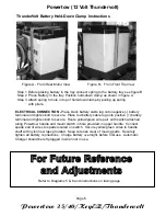
Page 8: ...wire ties clear of moving parts Securely tighten all battery connections Charge battery overnight before first use Automatic Charger should be left plugged in when not in use Powertow 12 Volt Thundervolt F Fo or r F Fu ut tu ur re e R Re ef fe er re en nc ce e a an nd d A Ad dj ju us st tm me en nt ts s Figure A From Rear Motor View Figure B From Front Tire View Step 1 Before placing battery in th...

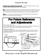
Page 9: ...r and you won t have to store gasoline just for the Powertow Powertow Gas Units ENGINE OR MOTOR TRANSMISSION ALL PULLEYS DIAGRAM 5 PULLEY ALIGNMENT F Fo or r F Fu ut tu ur re e R Re ef fe er re en nc ce e a an nd d A Ad dj ju us st tm me en nt ts s Pulley Refer to Diagram 5 Place a straight edge on the bottom surfaces of the motor pulley transmission and idler pulley visually check to assure pulle...

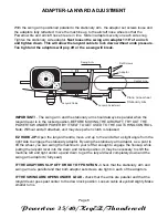
Page 10: ...osition BEFORE MOVING THE AIRCRAFT TRY OUT THE POWERTOW UNDER POWER BY ITSELF TO GET USED TO THE CLUTCHING CONTROL Note Without aircraft attached unit may creep when clutch is released EZ HOOK UP Open the lanyard handle move unit up to the aircraft at a slight angle from the right side to engage the stationary adaptor By using the stationary arm adaptor as a pivot to lift the wheel you can swing t...

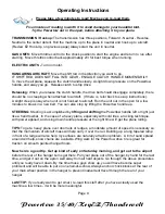
Page 11: ...utes to break in a new belt You can also stop by lifting the Powertow handle up STEERING Steering is accomplished by lifting and shifting the Powertow handle left or right just like a hand towbar In the case of a heavy plane especially with cold tires a rocking technique with power applied and using down handle pressure at the right time will get the plane rolling TIPS To get a heavy plane over do...

Page 12: ...oor Facing the aircraft in the same direction as it will be hangared mark the hangar floor indicating the exact centerline of the right main gear tire only Pull the aircraft out and paint a single stripe on the centerline of the right main only starting approximately 10 out from hangar door and back as far as main wheel would normally go Only this single point of alignment needs to be checked prog...

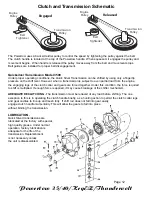
Page 13: ...However when a transmission is subject to even partial load from the engine the engaging lugs of the clutch collar and gears are forced together Under this condition the force required to shift is multiplied If enough force is applied it may cause breakage of the shifter mechanism ADEQUATE DECLUTCHING The transmission must be relieved of any load before shifting The one exception to this is in ope...

Page 14: ... the amount of the full purchase price excluding freight providing the unit is received in new original condition Call for authorization number for return Gasoline engines are warranted only by the engine manufacturer Engine warranty included with unit Engine parts must be obtained from engine dealers Refer to Small Engine Services in local yellow page directory All other parts are warranted by NO...

Page 15: ...gainst pillow block on bottom of frame to hold secure Chain is too loose Check sprocket alignment Shorten Clutch Cable by adjusting turnbuckle at handle Adjust cable so clutch is fully engaged with approximately 1 of space remaining between clutch handle and machine handle grip Need new belt See clutch cable this page Check to make sure motor transmission and idler pulleys are in line Belt is insi...

Page 16: ...es into hangar walls 9 Do not change gearing to increase speed 10 Do not move planes up any inclines flat surface only 11 Do not attach any device to activate throttle when both hands are not on throttle control 12 Do not run engine without checking oil level 13 Do not spill gasoline on hot engine 14 Do not smoke when filling tank with gasoline 15 Use caution when operating machine on icy slippery...

Reviews: