Powertow 35/40/KeyEZ/Thundervolt
Powertow 35/40/KeyEZ/Thundervolt
Page 4
DETAILED ASSEMBLY DIAGRAMS
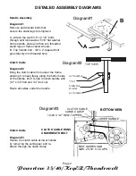
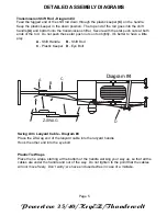
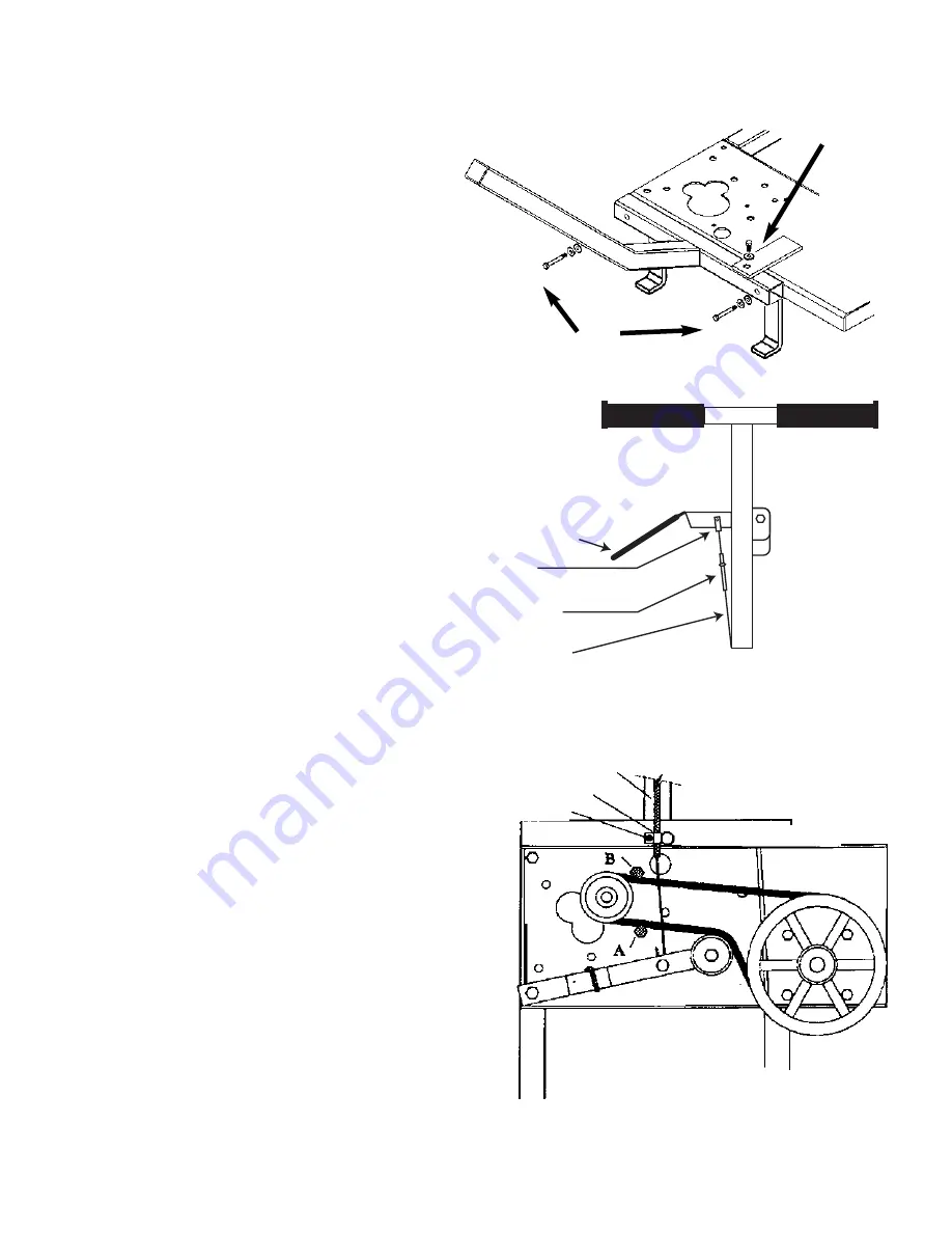
Handle Assembly
Diagram #1
Remove and discard bolts that
secure the stand legs for shipment
A - Attach the two 5/16” x 2 1/4” bolts
through split lock washer, 5/16” flat washer,
frame handle, plate and then into threaded
stand legs or frame caster wheels.
B - Top handle bolt - 3/8” x 2” tapered bolt
goes directly into threaded hole.
Diagram#1
A
B
Clutch Cable
Diagram #3
Secure the clutch cable at lower handle
by removing the self-tapper and re-
attach through the cable clamp.
CLUTCH CABLE
CABLE CLAMP
10/24 X 1/2” SELF-TAPPER
BOTTOM VIEW
LOWER HANDLE
BELT GUIDES A&B
SIZE: 2 5/16” X 2 CAPS
CLUTCH CABLE RUNS
UNDERNEATH BELT
Clutch Cable
Diagram #2
Bring the clutch cable from under the frame,
allowing it to hang freely along the bottom side
of the handle. Bolt U-Clip to clutch handle with
1/4" x 3/4” bolt and 1/4" lock nut.
Route all cables under the handle.
CLUTCH HANDLE
"U" CLIP
TURNBUCKLE
ADJUSTER
CLUTCH CABLE
TOP VIEW
Diagram#2
Diagram#3


