Service Manual
Chapter 1 - Overview
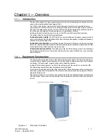
Equipment Construction
1 - 2
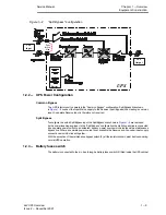
3x3 UPS Overview
Issue 2 - November 2001
1.2.1 - Principle of operation
Normal operation
During normal operation, i.e. when the UPS input supply is present and within specification, both the
converter and inverter sections are active and the automatic byĆpass is turned on to connect the inverter
output to the critical load terminals. The battery fuseĆholder switch is also closed and the battery is thereĆ
fore permanently float charged at the d.c. terminals voltage level.
Mains Failure
If the mains has a failure or is out of tolerance the converter will be supplied from the battery, while the
Inverter will continue to operate for a period of time which depends on the load and the capacity of the
battery. If the mains supply has not returned within this time, the Inverter will go off automatically and
an alarm condition will appear on the UPS operator control panel.
Critical load will not be interrupted in the event of a drop or return of the AC power mains.
Return of power mains
When the mains returns within the required tolerance, the converter will be automatically supplied from
mains, supplying power to the Inverter and recharging the battery at the same time. There will be no
interruption of the critical load.
UPS fault
In the event of an inverter failure, the automatic byĆpass will automatically transfer the load onto the
mains with no interruption. In such an event, request qualified technical assistance.
The load will be transferred with no interruption if the inverter is synchronised with the mains; if this is
not the case, there will be an interruption of some milliseconds.
The intervention of the automatic byĆpass line is shown on the front panel by the yellow led on.
WARNING
CAUTION
: When the load is being supplied from the bypass line through the automatic byĆ
pass, it is connected directly to the mains supply and is therefore no longer protected
against mains faults.
Maintenance Bypass
A second bypass circuit contained in the UPS cabinet, identified as the 'Maintenance Bypass' line is
included to enable the reserve supply to be made available to the load while facilitating a safe working
environment for carrying out scheduled UPS system maintenance or trouble shooting. The circuit is
manually selected by the Manual Bypass Switch (3) which can be padlocked in the OFF position.
WARNING
CAUTION
CAUTION: If an automatic circuit breaker device is not present in the input disĆ
tribution panel, there remains a dangerous voltage at the output terminals and also on the
input terminals of the UPS module that is switched off.
Note: The load is not protected from mains aberrations when operating on the
maintenance bypass mode.


