Service Manual
Chapter 1 - Overview
Equipment Construction
1 - 3
3x3 UPS Overview
Issue 2 - November 2001
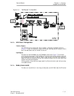
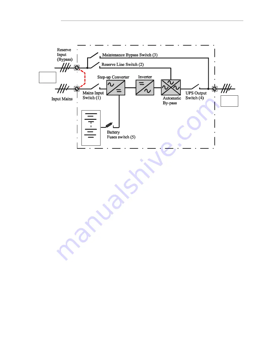
Figure 1-2
Split Bypass" configuration
UPS
Output
UPS
Input
Battery
UPS
Split
Bypass
Link
1.2.2 - UPS Power Configuration
Common Bypass
The UPS is factory set to operate in the Common Bypass" configuration. Split Bypass links shown
in
Figure 1-2
connect the Input Mains supply to the Reserve Input (Bypass) line creating a common
input. A separate Reserve Input is therefore not required.
Split Bypass
To configure the with a Split Bypass input, the Split Bypass links shown in
Figure 1-2
are removed
by the commissioning engineer. In the Split Bypass" configuration the static bypass line is connected
by a separate power switch to a dedicated `bypass' power source which also feeds the maintenance
bypass line. Where a separate power source is not available the Reserve and Converter input supply
connections would be linked together.
With the exception of the maintenance bypass switch (3), all the isolators shown must be closed during
normal UPS operation.
1.2.3 - Battery fuses switch
The battery is connected to the d.c. bus through a battery fuses switch (5) fitted inside the UPS cabinet


