Service Manual
Chapter 2 - Installation
Battery Installation
2 - 10
3x3 UPS Installation
Issue 2 - November 2001
Battery Tray Assembly
1.
Place the Mylar insulation strip on to the battery tray.
2.
With a DVM check each individual battery block terminal voltage is within 12.5V to 13.0V.
Voltages measured below this may indicate a defective battery block. Refer to
`Battery
Maintenance' on Page 6Ć5 Chapter 6 `Maintenance'
for information on battery testing.
3.
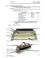
Fold the mylar insulation to fit the batteries and place the 11 battery blocks on to the battery
tray, as shown in
Figure 2-5
(Note 10 battery blocks are fitted to the top battery tray.
4.
Stick the adhesive foam strip to the battery fixing bracket.
5.
Screw the battery retaining bracket to the battery tray.
Connect the batteries using the short battery interconnecting links.
6.
Fit the lexan protection to the battery fixing bracket.
7.
Place the three adhesive cable retaining clips to the lexan insulating strip, one in the middle
and one at each end.
8.
Identify the cable Anderson type connecter supplied with a red and black interconnecting
cable and connect the red cable to the remve battery connection and the black
cable to the ćve battery connection.
9.
Secure the cables in the cable retaining clips.
10. Secure the red cable to the battery retaining bracket at the rear of the assembled battery tray
using a cable tie supplied.
11. Stick the `High Voltage' label to the lexan insulating strip.
Repeat the above procedure for the remaining two battery trays.
Note: The upper battery tray is fitted with 10 batteries.
Battery String Connection
1.
Ensure that the UPS has been powered down.
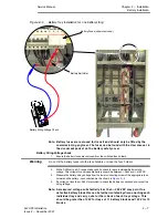
Note: When positioning the battery trays in the UPS, slight downward pressure
may be required on the front of the tray to clear the chassis metalwork at
the rear.
2.
Fit the lower battery tray of 11 batteries to the lower position and secure using the battery
tray retaining bolt.
3.
Fit the second battery tray of 11 batteries to the middle position and secure using the battery
tray retaining bolt.
4.
Fit the upper battery tray of 10 batteries to the top position and secure using the battery tray
retaining bolt.
5.
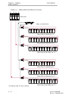
Refer to the schematic diagram (
Figure
) locate the battery string interconnecting links from
the battery cable set.
6.
Thread the Red +ve wire of the lower Anderson type cable connector through the
appropriate access hole and connect it to the battery fuse lower cable terminal.
Note: Fuse F1 is used for the first battery string, F2 for the second etc.
7.
Thread the Black ćve wire of the top Anderson type cable connector through the appropriate
access hole and connect it to the ćve battery connection bar cable stud.
8.
Connect the wiring harness connectors to the battery tray Anderson connectors.
a)
CN1 to the top battery tray.
b)
CN2 to the middle battery tray.
c)
CN3 to the lower battery tray.
9.
Secure the Anderson type battery connectors to the battery retaining bracket using the cable
ties supplied with the kit.


