Service Manual
Chapter 3 - Commissioning
Validating the Installation
3 - 2
3x3 UPS Commissioning
Issue 2 - November 2001
3.3 - Setting UPS Parameters
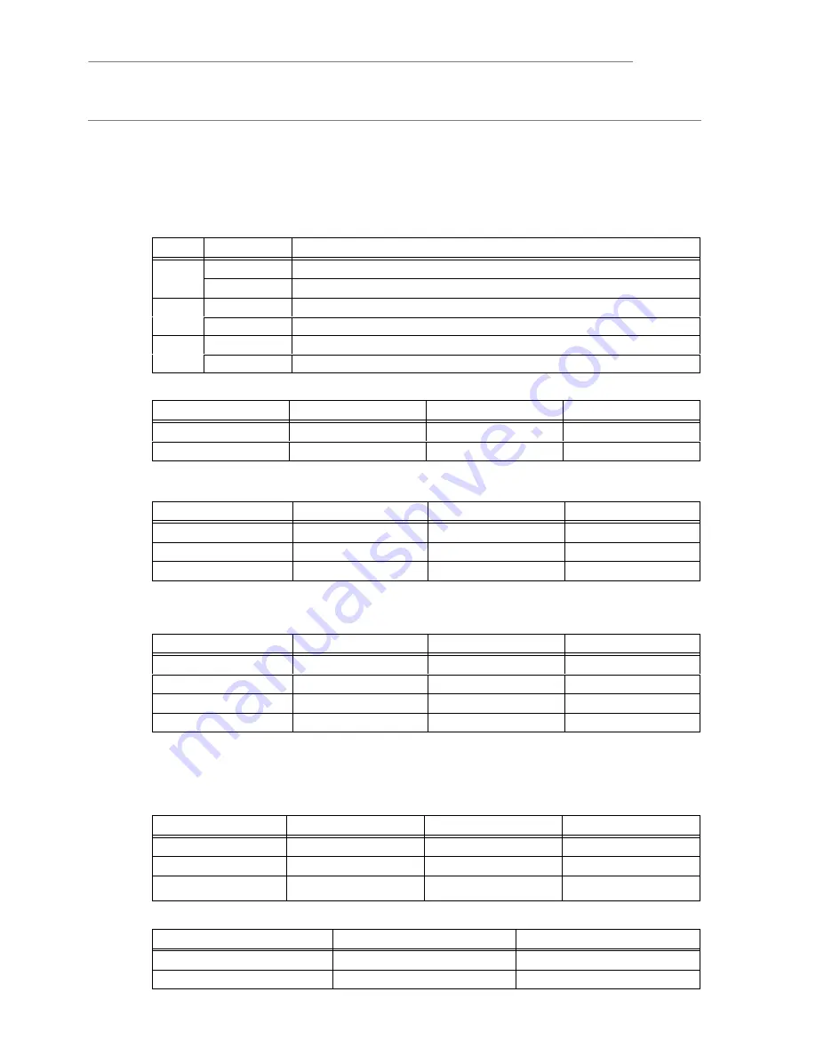
Check that the following factory set parameters are correct for the normal operating Conditions of the UPS.
Standard link positions are shown in bold text.
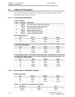
3.3.1 - Control Logic PCB CS0072.
General Operation:
LINK
POSITION
FUNCTION
J1
OPEN
Eco mode operation (bypass line preferred)
J1
CLOSED
Normal operation (inverter line preferred)
J2
OPEN
Bypass frequency window 4%
J2
CLOSED
Bypass frequency window 1%
J3
OPEN
Inverter output frequency 60Hz
J3
CLOSED
Inverter output frequency 50Hz
Output voltage selection:
Link
380Vac
400Vac
415Vac
J4
Open
Closed
Open
J5
Closed
Open
Open
The following link position set the UPS overload level relative to the UPS kVA rating. (As shown
on the factory rating plate)
Link
10kVA
20kVA
30kVA
J6
Open
Closed
Open
J7
Closed
Open
Closed
J8
Closed
Closed
Open
The following link position set the inverter and converter peak current limits which is dependent
on the UPS kVA rating. (as shown in the factory rating plate). Ensure that these links are set
according to the following table:
Link
10kVA
20kVA
30kVA
J9
Open
Open
Open
J10
Open
Open
Open
J11
Closed
Closed
Closed
J12
Closed
Closed
Closed
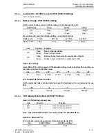
3.3.2 - Driver Interface PCB CS0071 Settings
Bypass value setting
Link
380Vac
400Vac
415Vac
J1A
Closed
Open
Open
J2A
Open
Closed
Open
J3A
Open
Open
Closed
Service / test mode for the secondary DC bus voltage
DC V/Link
J4A
J5A
375 Vdc
Closed
Closed
750Vdc
Open
Open

