Service Manual
Chapter 6 - Maintenance
Scheduled Maintenance
6 - 5
3x3 UPS Maintenance
Issue 2 - November 2001
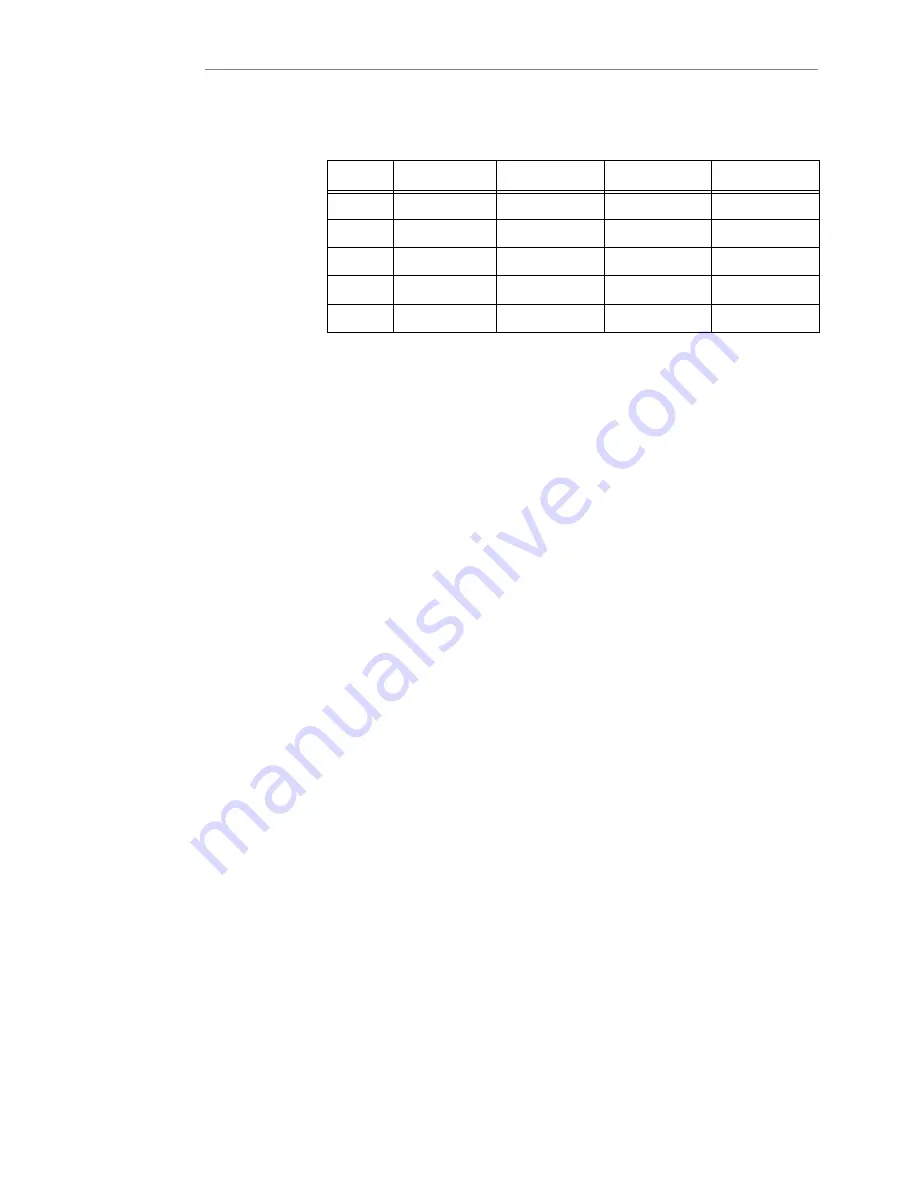
Table 6-1
Output Voltage PCB Link Settings
Link
PCB Part Nº
38OVac
400Vac
4l5Vac
J4
CS0072
open
close
open
J5
CS0072
close
open
open
JIA
CSOO7I
close
open
open
J2A
CSOQ7I
open
close
open
J3A
CSOO71
open
open
close
lnverter Bypass Phase Lock check
1.
Using a dual trace oscilloscope operating in the differential mode (insulated from mains) on
the inverter driver interface PCB (CSOO7I) connect:
a)
Probe 1 to the bypass `R' phase voltage terminal stud N9.
b)
Probe 2 to the inverter output phase `R' voltage terminal stud N 7.
2.
Check both sine waves are perfectly in phase.
The phase adjustment is fixed and is determined by R23 on the driver interface CSOO7I (1
Mohm).
The check of the CONVERTER and INVERTER section is now complete.
Battery charger checks
Float voltage adjustment and battery reĆcharging current
1.
Connect a DVM set to DC volts to the battery DC bus terminal connecting block (terminal 6Ć7
positive, 8Ć9 negative).
2.
Open the battery power fuses F1 to F4.
3.
Check that the value at the battery DC bus terminal connections is 432 Vdc
±
1%.
If the measured value is different it is possible to reĆadjust using the potentiometer P1 on the
battery charger PCB C50074.Ć
Note: Turning P1 CCW will increase the float voltage
4.
Refit the battery fuses.
5.
Check the battery reĆcharging current with a DC clamp meter.


