background image

Service Manual

Chapter 6 - Maintenance

Battery Maintenance

6 - 6

UPS Maintenance

Issue 2 - November 2001

6.2 - Battery Maintenance

The batteries fitted within the UPS are valve regulated and require very little maintenance.
It is wrong to describe them as completely `maintenance free', because the batteries still require a mainĆ

tenance check, but at a significantly greater interval than the unsealed type.
The removal of the need to continually top up batteries, is a major advantage, but by removing access,

a visual examination of the cell plates, and electrolyte is impossible.
Battery condition and capacity can therefore only be determined as a complete 12V battery block.
The battery is an important component in the UPS system, as the UPS function relies on the battery

power, on failure of the input AC supply To ensure that the battery will support the UPS operation it should

be checked annually for performance.

6.2.1 - Factors Effecting Battery Use

The following factors affect the overall operation and ultimately the useful life of the UPS battery. These

considerations must be taken into account when deciding the serviceability of a battery.

Service life

Temperature is the major factor in determining the effective life of a battery if the battery is operating

above 200 C it will reduce the battery life. It is also important that the charge voltage is within limits. TypiĆ

cally a 5 year life battery will start to decline after 3 years in service, therefore the need for regular checks

is important.

Charge voltage

The nominal charge voltage is normally 2.25 volts per cell, multiplied by the number of cells in series.

Operation at voltages below 2.2 volts per cell, will lead to a undercharge and sulphation. Operation at

2.3 volts per cell and above, will cause overcharge and rapid positive plate corrosion. Positive plate corĆ

rosion is known to be the major life limiting component in all batteries, therefore for optimum life, battery

cell voltages must be within the range of 2.25 to 2.3 volts per cell.
The UPS has 32 x 12V batteries and is designed to operate with a float charge voltage of 432 V

DC.

Battery capacity

Battery capacity is used to define endĆofĆlife of the battery for example if the battery cannot supply 80%

it is deemed to be at the end of its effective life. For some applications 80% may be decreased to 50%

to mark the end of the batteries effective life.
Battery capacity from manufacture, usually increases slightly after 2 or 3 discharges and will be enĆ

hanced by high temperature and reduced by low temperature.
As the battery ages beyond 12 months the battery capacity will fall at a rate determined by the operating

temperature and the charge voltage. These adverse factors, will cause accelerate erosion to the positive

plate grid, reducing the effective battery capacity The life of the battery will then depend on the requireĆ

ments of the system, if the capacity of the UPS has been oversized then the load may only need 50%

of the normal duty.
In most applications, the battery is essentially on continuous float charge, and rarely will experience a

input supply failure longer than the end of the battery autonomy.
Therefore a battery in poor condition may well continue to support the load for short autonomies, but

will fail if the loss of the input AC supply exceeds 30 seconds.
It is therefore highly recommended that a battery autonomy test, is carried out as part of a regular mainĆ

tenance program.

Open circuit voltages

Measurement of the battery open circuit voltage is not a good indicator of the available capacity of the

battery It may apply to batteries on the shelf but not to batteries that have been on charge, up to 72 hours

prior to measurement. The terminal voltage of batteries that have been on charge, have an actual cell

voltage, plus a polarization voltage.

Summary of Contents for 10kVA

Page 1: ......

Page 2: ......

Page 3: ... DATED S IN ORDER TO ENSURE THAT YOU RECEIVE ANY AMMENDMENT PLEASE REGĆ ISTER THIS MANUAL WITH THE TECHNICAL SUPPORT DEPARTMENT BY REĆ TURNING A COPY OF THIS FORM TO Manual Registration Number Name of Registered Holder Address of Holder Company Name Building Street Road Area region Town City County State Post Zip Code Country Telephone Number FAX Number E Mail Address ...

Page 4: ...Amendment Record Amendment Record Service Manual Manual Serial Number Please enter the Manual Serial Nº for future record Issue Nº Issue Date Amendment Amended By Date 1 Initial issue ć ć ...

Page 5: ...age iii 3x3 UPS Preliminary Pages This Service manual contains information concerning the installation operation and service of the folĆ lowing UPS EQUIPMENT PART NUMBER With battery Without battery 10 kVA UPS 15 kVA UPS 20 kVA UPS 30 kVA UPS ...

Page 6: ...ith local electrical codes WARNING This UPS does not incorporate automatic backĆfeed protection A warning label must be fitted to all external primary power isolators stating ISOLATE THE UNINTERRUPTIBLE POWER SYSTEM BEFORE WORKING ON THIS CIRCUIT The UPS should not be supplied from electrical power systems of the IT Impédance à Terre type IEC 364 Ć ELECTRICAL INSTALLATION OF BUILDINGS Note Where u...

Page 7: ...attery manufacturers supply details of the necessary precautions to be observed when working on or in the vicinity of a large bank of battery cells These precautions should be followed at all times Particular attention should be paid to the recommendations concerning local environĆ mental conditions and the provision of protective clothing first aid and fireĆfighting facilities TEST EQUIPMENT When...

Page 8: ...nel The Troubleshooting section and Service procedures contained in this manual are norĆ mally outside the scope of personnel categorised competent though they may be aware of the dangers appropriate to working with hazardous voltages A Competent engineer is deemed to have sufficient technical skills training to make electrical connections install batteries close and open circuit breakers fuses et...

Page 9: ...ility Static Balanced Load Static 50 Unbalanced Load Static 100 Unbalanced Load Dynamic 50 Load Step Dynamic 100 Load Step 1 3 5 3 5 Output Voltage Transient Recovery Time 30ms to 3 RMS Output Voltage Distortion THD Linear Load Non Linear Load 100 3 1 Crest Factor Load 3 5 Output Voltage Phase Displacement Balanced Load 100 Unbalanced Load 120 1 120 3 Nominal Output Frequency 50 or 60Hz Output Fre...

Page 10: ...age Ripple 1 Maximum Battery Recharging Current 1 3 5 or 7A Selectable Automatic Battery Test 12 24 or 48 hour impedance test System Data Topology True OnĆline double conversion high frequency transformerless design Power Upgrade Yes ć up to a maximum rating of 30kVA StartĆup On Battery Yes System Efficiency Excluding Battery Charging 50 Linear Load 100 Linear Load 88 90 88 90 89 91 90 91 Full Loa...

Page 11: ...0 mm Unit Weight Without Battery 185kg Unit Weight With Standard Battery 275kg 365kg 365kg 455kg Shipping Dimensions w x h x d 545 x 1260 x 965 mm Unit Shipping Weight Without Battery 215kg Unit Shipping Weight With Standard Battery 305kg 395Kg 395kg 485kg Enclosure Rating IP20 Colour RAL 7035 Metal Covers RAL 7042 Plastic Door Design Standards Safety Radio Frequency Interference RFI Electromagnet...

Page 12: ...6 UPS with 4 internal sets of batteries 3 BATT 41 57 94 191 600 3 Phase 15kVA UPS with 2 internal sets of batteries Standard configuration 9 14 24 55 157 UPS with 3 internal sets of batteries 1 x BATT 17 24 40 91 269 UPS with 4 internal sets of batteries 2 x BATT 24 35 56 128 398 3 Phase 20kVA UPS with 2 internal sets of batteries Standard configuration 6 9 17 39 108 UPS with 3 internal sets of ba...

Page 13: ...s 2 5 2 3 Battery Installation 2 6 2 3 1 Battery Safety 2 6 2 3 2 Battery Installation Check 2 6 2 3 3 Installing the Battery Upgrade Kit BATTCABLE 2 9 2 4 Setting Standard Relay Interface PCB 2 12 2 4 1 Setting Options on the standard Relay Interface 2 12 2 4 2 Relay Interface Connections 2 13 2 4 3 Remote EPO Emergency Power Off 2 14 2 4 4 Emergency Power Off E P O pushĆbutton connection 2 14 2 ...

Page 14: ... 1 4 1 Operator Control Panel 4 1 Chapter 5 Functional description 5 1 5 1 Control Logic PCB CS0072 5 1 5 1 1 Potentiometer adjustment 5 1 5 1 2 Link and Jumper functions 5 1 5 2 Auxiliary Supply PCB CS0070 5 2 5 2 1 Battery Threshold settings 5 2 5 3 Driver Interface PCB CS007I 5 3 5 3 1 Bypass Voltage Threshold Adjustment 5 3 5 3 2 Link and Jumper functions 5 3 5 4 Battery Charger CS0074 5 4 5 4...

Page 15: ...26 7 8 7 Checking power circuit capacitors 7 27 7 9 PCB Replacement Procedures 7 28 7 9 1 Auxiliary DC Ć DC Converter Part Nº OSDE0070 PCB Label CS0070 Exx 7 28 7 9 2 LCD UPS Monitor Board OSDE0077 PCB Label CS0077 Exx 7 29 7 9 3 Inverter Driver Feedback Interface Part Nº OSDE0071 7 30 7 9 4 3ph TL Control Logic Part Nº OSDE0072 PCB Label CS0072 Exx 7 32 7 9 5 Battery Charger Part Nº OSDE0074 PCB ...

Page 16: ......

Page 17: ...noise present on the input utility supply line is effectively isolated from the UPS output therefore the critical load sees only clean power Powewr blackout protection If the utility power fails the UPS continues to power the critical load from its backĆup battery source leaving the load immune from power disturbances ć even complete power blackouts 1 2 Equipment Construction The equipment is cons...

Page 18: ...ruption of the critical load UPS fault In the event of an inverter failure the automatic byĆpass will automatically transfer the load onto the mains with no interruption In such an event request qualified technical assistance The load will be transferred with no interruption if the inverter is synchronised with the mains if this is not the case there will be an interruption of some milliseconds Th...

Page 19: ... Bypass To configure the with a Split Bypass input the Split Bypass links shown in Figure 1 2 are removed by the commissioning engineer In the Split Bypass configuration the static bypass line is connected by a separate power switch to a dedicated bypass power source which also feeds the maintenance bypass line Where a separate power source is not available the Reserve and Converter input supply c...

Page 20: ......

Page 21: ...as instructed on the outer case UP DOWN 2 Cut the tape and open the flaps at the top of the cardĆboard box 3 Remove the extruded elements used as protective packing 4 Position the forks of the lifting truck under the UPS taking care not to damage the UPS castors and lift it a few centimetres from the floor Back up the forklift and position the UPS Lower to the floor Hinet is provided with wheels t...

Page 22: ... at maximum efficiency in this temperature range Clearances Cooling air enters the module through ventilation grills located at the bottom of the cabinet and is exĆ hausted through the fan grills located on the front panel you must therefore allow for a minimum gap of 170 mm behind the unit to allow adequate air flow Clearance around the front of the equipment should be sufficient to enable free p...

Page 23: ...1 16 W1 17 N1 Caution When preparing the power cables for connection provide sufficient spare cable to allow the UPS to be moved if necessary from it s normal operating position for servicing access Spare cable can be coiled beneath the unit 3 Tighten the terminal block lower securing screws and check that each cable is secure 4 Connected the UPS Output power cables to terminals 1 U2 2 V2 3 W2 4 N...

Page 24: ...put reserve Bypass phase U3 3 Output phase U2 4 Input reserve Bypass phase V3 5 Output phase V2 6 Input reserve Bypass phase W3 7 Output phase W2 8 Input Reserve Bypass Neutral N3 9 Output Neutral N2 10 Input Mains phase U1 11 Battery Positive ext Battery input 12 Input Mains phase V1 13 Battery Positive ext Battery input 14 Input Mains phase W1 15 Battery Negative ext Battery input 16 Input Mains...

Page 25: ...RSONNEL OR THE RISK OF FIRE SHOULD AN EARTH FAULT OCCUR BEFORE ANY OTHER CABLE CONNECTION THE PE SAFETY CONDUCTOR SHALL BE CONNECTED 2 2 4 Protective devices Protection against earth faults RCD devices In the event of a differential RCD device being installed upstream of the input supply the transient and steady state earth leakage currents that are produced during startĆup of the UPS must be take...

Page 26: ...quipment S When connected together the battery terminal voltage will exceed 380Vdc and is potentially lethal S Eye protection should be worn to prevent injury from accidental electrical arcs S If a battery leaks electrolyte or is otherwise physically damaged it should be placed in a container resistant to sulphuric acid and disposed of in accordance with local regulations S If electrolyte comes in...

Page 27: ... the fuse holders or close the fuse holders 2 With a DVM set to a DC range of above 450V check for each individual battery string voltage This voltage for a serviceable battery should be between 385V and 416V DC 3 Measure the battery string voltage from the lower connecting screw of the appropriate fuse holder and the battery ćve connection bar As shown in Figure 2 3 4 If a voltage of less than 38...

Page 28: ...Battery Tray 11 CN1 CN2 CN3 Note Battery strings 1 3 shown connected Battery String 1 Top Battery Tray 10 Battery String 1 Middle Battery Tray 11 Battery String 1 Bottom Battery Tray 11 CN1 CN2 CN3 Service Manual Chapter 2 Installation Battery Installation 2 8 3x3 UPS Installation Issue 2 November 2001 Figure 2 4 Battery Cable Connections for one string ...

Page 29: ...r insulating sheet CM 0319 3 Battery tray CM 0470 3 Battery retaining bracket CM 0743 3 Lexan protection CM 0101 3 Battery cable harness OS 001 1 Adhesive foam strip ć Cable holder self adhesive 9 Label High Voltage 3 Note The 32 battery blocks are not included in the upgrade kit Part Nº BATTCABLE but are supplied separately as Battery Kit Part Nº INTBATT Figure 2 5 Battery Tray Assembly Mylar Ins...

Page 30: ...plied 11 Stick the High Voltage label to the lexan insulating strip Repeat the above procedure for the remaining two battery trays Note The upper battery tray is fitted with 10 batteries Battery String Connection 1 Ensure that the UPS has been powered down Note When positioning the battery trays in the UPS slight downward pressure may be required on the front of the tray to clear the chassis metal...

Page 31: ...ble battery should be between 385V and 416V DC 3 Measure the battery string voltage from the lower connecting screw of the appropriate fuse holder and the battery ćve connection bar As shown in Figure 2 3 4 If a voltage of less than 385V is recorded reĆcheck the battery connections and reĆtest the string voltage Note A measured voltage substantially less then 385V DC may point to a defective batte...

Page 32: ...eft side of the rear panel This card is typically supĆ plied and is factory preĆset to operate with the PC When the operation is through the remote indication panel the factory will deliver the card already preset to operate with the remote panel Figure 2 6 Setting options on the standard Relay Board FUNCTION JUMPER CLOSED JUMPER OPEN Use With PC JP4 JP5 Use With Remote Panel JP5 JP4 EPO Enabled ć...

Page 33: ...face PCB provides two sets of volt free contacts rated at 50V 1A the PCB receives the UPS status signals from the Display Control Logic PCB Part Nº CS0073 and is connected to CN1 Output signals from the relay interface are made to the terminal block M1 shown in Figure 2Ć7 or from the RS232 DB9 connector P1 fitted to later equipment only Figure 2 7 Relay Interface Outputs ...

Page 34: ...e EPO switch Do not remove cover from these parts Only competent personnel must remove protection panel held in place with screws 2 4 4 Emergency Power Off E P O pushĆbutton connection Refer to Figure 2 6 and Figure Figure 2 7 to make a pushĆbutton connection to the standard Relay Card 1 Obtain a suitable length not more than 100 m twoĆwire cable 0 6 sq mm cross section 2 Connect one end of the ca...

Page 35: ...y is used in applications requiring the UPS to provide status and power monitoring informaĆ tion to the computer system For example during a mains power failure the information can be used by the computer s operating system or application program to automatically save information in buffers to close files and shutdown operations prior to battery capacity depletion Monitoring of the UPS via a compu...

Page 36: ......

Page 37: ...n in this manual 3 2 1 Positioning 1 Check that the UPS has been correctly positioned with at least 150mm clear space at the rear 2 Check that there is sufficient space at the sides of the unit to gain access If no access is available the UPS input and output cabling must be of sufficient length to allow the unit to be moved forward 3 2 2 Preliminary checks 1 Ensure that all the UPS isolators incl...

Page 38: ...400Vac 415Vac J4 Open Closed Open J5 Closed Open Open The following link position set the UPS overload level relative to the UPS kVA rating As shown on the factory rating plate Link 10kVA 20kVA 30kVA J6 Open Closed Open J7 Closed Open Closed J8 Closed Closed Open The following link position set the inverter and converter peak current limits which is dependent on the UPS kVA rating as shown in the ...

Page 39: ...compensation disable JP4 Closed Battery charger temperature compensation enable Battery test settings Links JP5 to JP10 set the capacity of the standard battery check the battery Ah to set the corĆ rect value as shown in the table below Link JP10 JP9 JP8 JP7 JP6 JP5 Ah 7 2Ah 2x7 2Ah 3x7 2Ah 4x7 2Ah 38Ah 65Ah JP11 SHOULD BE ALWAYS CLOSED Set the automatic battery test interval referring to the tabl...

Page 40: ...abled a d 3 4 1 Converter and Inverter Output Calibration The Secondary DC bus and Inverter Output settings will be automatically set by the Voltage parameters set on the UPS Control Boards see Setting UPS Parameter Section for more details The following table shows the correct levels of the Inverter AC volts and the Secondary DC Bus volts depending on the Voltage Parameters Voltage Parameter Inve...

Page 41: ...started and be brought on line f Press CLEAR d twice to return to the main menu 5 Wait 20 seconds and confirm that D The Green LOAD on INV LED has illuminated D Using the DVM check that the Secondary DC has risen to within 1 of the appropriate level shown in the table above e g 750Vdc for a 400Vac installation If required the level of the secondary DC bus can be adjusted using the Potentiometer P2...

Page 42: ... The Zero crossings of the Inverter and Bypass sinewaves are synchronised 3 4 3 Battery Charger Output Calibration The following procedure describes the calibration of the UPS s Battery charger output Connecta DVM set to DC Volts to the UPS s External Battery terminals ve at terminals 6 or 7 and ćve at terminals 8 or 9 Ensure that D The DC value at the battery terminals is at 432Vdc 1 If required ...

Page 43: ...luminate D The green LOAD on INV LED 3 remains illuminated D The alarm buzzer should sound press CLEAR d push button to silence the alarm 3 Using a DVM check that the output Voltage and frequency at output terminals is correct e g 400Vac and 50Hz 4 Close the RESERVE INPUT MCB I2 5 The UPS should now return to normal Operation Ensure that D The ć UPS in Operation ć returns to the LCD D The green NO...

Page 44: ...tomatic By pass circuit to switch and then checking that the load is still being powered If no other alarms occur the UPS will automatically re transfer back to inverter operation after 20 seconds on completionof the test 1 Press the MENU push button a on the FRONT PANEL a Select the COMMAND screen by pressing either the BACK c or NEXT b push button b Confirm the COMMAND menu selection by pressing...

Page 45: ...h button e Confirm INVERTER OFF function by pressing BACK and NEXT at the same time D A CONFIRMED message will be displayed f Press CLEAR twice to return at the main screen 4 The follow sequence should occur D The Alarm buzzer is activated D The Red general ALARM red LED 2 will illuminate D The Yellow BYPASS ON LED 4 will illuminate D The Green NORMAL LED will extinguish D The LCD will display the...

Page 46: ...D The red ALARM LED has illuminated D The green NORMAL LED has extinguished D The green LOAD on INV has extinguished D The LCD shows the alarm EMERGENCY POWER OFF To restart the UPS after an EPO carry out the following procedure 1 Open the UPS OUTPUT MCB I4 2 Open the INTERNAL BATTERY fused switch I5 3 Open the RESERVE INPUT MCB I2 4 Open the MAINS INPUT MCB I1 D Wait until the display has de ener...

Page 47: ...e status of the UPS Operator Panel D The Amber BYPASS ON 4 LED will be illuminated D The red ALARM 2 led will be illuminated D The LCD will display the following messages MAINS WITHIN LIMITS BY PASS LINE WITHIN LIMITS BATTERY VOLTAGE WITHIN LIMITS LOAD ON BY PASS and INVERTER OFF 7 To Silence the buzzer press the CLEAR d push button 8 To Start the Inverter carry out the following instructions a Pr...

Page 48: ... CLEAR d twice to return to the main menu The following change over sequence should occur indicating that the load has been transfer to the bypass line D The yellow BYPASS ON LED 4 is illuminated D The green LOAD on INV LED is extinguished 3 To turn off the Inverter follow the procedure below a Press the MENU push button a on the FRONT PANEL b Select the COMMAND screen by pressing either the BACK ...

Page 49: ... on the FRONT PANEL b Select the COMMAND screen by pressing either the BACK c or NEXT b push button c Confirm the COMMAND menu selection by pressing BACK and NEXT at the same time i e ENTER d Select the INVERTER ON OFF screen by pressing either the BACK c or NEXT b push button e Confirm INVERTER ON function by pressing BACK and NEXT at the same time D A CONFIRMED message will be displayed f Press ...

Page 50: ... table Output signals from the relay interface are used for the control of customer peripheral computer equipment and connections are made to the terminal block M1 shown in Figure 3Ć6 or from the RS232 DB9 connector P1 fitted to later equipment only Figure 3 5 Setting options on the Relay card Table 3 1 Relay Interface PCB Output Relay UPS Function Signal Function Link Relay UPS Function Signal Fu...

Page 51: ...vember 2001 Table 3 2 Serial Port P1 DB9 Connector Connections Pin F ti R l Link Pin Nº Function Relay JP1 JP2 JP3 JP4 JP5 5 COMMON N A Closed ć ć 3 UPS RX N A ć Closed ć ć 2 UPS TX N A ć ć Closed 8 9 MAINS STATUS RL1 ć MainsĆ NOK MainsĆOK 1 7 PRE ALARM RL4 ć Figure 3 6 Relay Interface Outputs ...

Page 52: ......

Page 53: ...onsists in a LCD display that indicates the operational and alarm status of the UPS and the EPO push button that is located at the left side The LCD Display Panel displays textual messages and operating parameters on a LCD screen capable of showing 4 rows of 20 characters The displayed screen is organized in a multi level menu system and selected by using push button located to the right of the sc...

Page 54: ...revious level To verify the acquisition of ENTER a Beep will be heard and CONFIRMED will appeared on the Display The NEXT BACK selector keys are used to scroll through different windows in the same menu Table 4 1 LCD Display Main Menu Path STATUS ALARM MENU MENU CLEAR ENTER NEXT BACK COMMAND MODE NEXT BACK EVENT HISTORY NEXT BACK OPERATING LANGUAGE NEXT BACK CLOCK NEXT UPS CONFIGURATION NEXT BACK ...

Page 55: ...ssage given are the following UPS in Operation MESSAGE INTERPRETATION MAIN WITHIN LIMITS The Main Input Line is present and the voltage is in the specified range BYPASS LINE WITHIN LIMITS The Input Bypass Supply Line is present and the volĆ tage is within the specified tolerance BATTERY VOLTAGE WITHIN LIMITS The Battery voltage is within specifications limits INVERTER OPERATING The inverter is tur...

Page 56: ...MERGENCY POWER OFF The Command EPO has been seĆ lected Restart the UPS Fully switch off the Breakers and the Battery Fuse wait till the LCD is complete switch off then restart the UPS BATTERY NOT CONNECTED Battery Switch Open Battery Test Failed BATTERY CHARGER FAULT Call Service Office to replace the Battery Charger HIGH BATTERY VOLTAGE LEVEL Battery Charger in Fault Call Service Office to replac...

Page 57: ... BACK DATE TIME PREVIOUS EVENT LAST 1 BACK BACK DATE TIME PREVIOUS EVENT LAST 2 MENU MENU ALARM STATE LAST EVENT MESSAGE 2 NEXT BACK ALARM STATE LAST EVENT MESSAGE M NEXT BACK NEXT ALARM STATE PREV EVENT N 1 MESSAGE 1 BACK ALARM STATE PREV EVENT N 1 MESSAGE 2 NEXT BACK ALARM STATE PREV EVENT N 1 MESSAGE M NEXT BACK ENTER CLEAR NEXT NEXT ALARM STATE PREV EVENT N 2 MESSAGE 1 BACK ALARM STATE PREV EV...

Page 58: ...d D Serial Number of the Unit D Telephone number of Service Dept D Battery Capacity Battery Ah at the C10 rate D Calibration Display calibration of the following parameters 1 Input Current and Voltage Calibration of measured Values 2 Output Current and Voltage Calibration of measured Values 3 Battery Current and Voltage Calibration of measured Values To enter in one of these menu follow the proced...

Page 59: ... a minimum The principal circuit functions of the control logic are a Feedback circuits inverter voltage converter voltage static bypass voltage inverter output current b Peak limit current detector circuits inverter current and converter current c Control logic power supply detector d Overload detector e UPS status and alarms generated by the UPS s PCB s 5 1 1 Potentiometer adjustment a P1 adjust...

Page 60: ...limit normally closed for all UPS output ratings 5 2 Auxiliary Supply PCB CS0070 The auxiliary power supply is based on a flyĆback converter circuit the source supply being the 750 volt DC Bus Secondary windings of the power supply transformer provide the control logic and the power componentgate drive circuits The auxiliary power supply generates a regulated 7 5Vdc and l5Vdc voltage Adjustments t...

Page 61: ...J6 for the static bypass c Input thyristor driver J16 d Converter DC feedback DC ĆDC e Inverter feedback f Bypass supply circuit and bypass threshold P1 and P2 g DC Bus unbalanced sensing SI reset 5 3 1 Bypass Voltage Threshold Adjustment a P1 adjusts the maximum bypass voltage threshold 10 b P2 adjusts the minimum bypass voltage threshold Ć10 5 3 2 Link and Jumper functions a J4AĆJ5A sets the DC ...

Page 62: ...432 Vdc 5 4 1 Battery Charger Voltage Adjustment a P1 adjusts the float voltage level to 432 Vdc b P2 adjusts the boost voltage level This setting is dependant on the type of battery fitted c P3 adjusts the float voltage when the temperature compensation option is enabled 5 4 2 Link and Jumper Functions a JPI ĆJP2 sets the recharging current Link Amper e IA 3A 5A JPI open open close JP2 open close...

Page 63: ... indicating that the battery is OK 5 5 UPS monitor board PCB CS0077 The function of UPS monitor board is to interface the UPS control and status alarm signals with the OperĆ ator LCD Control panel Part Nº CS0075 the Relay Interface PCB Part Nº CS0082 and the SNMP adapter SNMP CARD UPS CONTROL LOGIC P N CS0072 LCD MIMIC DISPLAY P N CS0075 UPS MONITOR BOARD CS0077 Inverter Driver Feedback CS0071 REL...

Page 64: ...o associated link Links fitted to the PCB allow the input mains status to be set and the serial port P1 to be enabled as shown in Table 5 2 These signals are generated on the display control logic PCB and connected to the relay PCB at connector CN4 Table 5 2 Serial Port P1 DB9 Connector Connections Pin F nction Rela Link Pin Nº Function Relay JP1 JP2 JP3 JP4 JP5 5 COMMON N A Closed ć ć 3 UPS RX N ...

Page 65: ...Service Manual Chapter 5 Functional description Relay Interface PCB CS0082 5 7 3x3 UPS Functional description Issue 2 November 2001 Figure 5 1 Relay Interface Outputs ...

Page 66: ...of this menu From the main menu the User may have access to different menu pressing the MENU Button second level Once in this level the first row will show menu choice and the NEXT and BACK push Button enable the User to move from one menu level to another Pressing both NEXT and BACK push button at the same time the ENTER command is selected and the next lower level will be reached while CLEAR tak...

Page 67: ...gested below will ensure optimum equipment performance and serve to detect minor malfunctions prior to them developing into a major fault 6 1 1 Daily Checks Carry out a daily walkĆby inspection of the UPS checking the following points 1 Carry out a spot check of the Operator Control Panel ensuring that all mimic LED indications are normal and no alarm messages are present 2 Check for obvious signs...

Page 68: ...tched OFF while the critical load is maintained To transfer the load to Maintenance Bypass 1 Press the MENU push button A on the FRONT PANEL a Select the COMMAND screen by pressing either the BACK C or NEXT b push button b Confirm the COMMAND menu selection by pressing BACK and NEXT at the same time i e ENTER c Select the SWITCH LOAD function by pressing either BACK or NEXT d Confirm SWITCH LOAD f...

Page 69: ...it until the fan is running indicating that the output voltage is present 2 Close the MAINS INPUT MCB I1 Wait until the Operator panel shows the following indications D LCD is energize and D The alarm buzzer sounds D The red ALARM LED 2 D The yellow BYPASS ON LED will illuminate 3 Close the INTERNAL BATTERY fused switch I5 4 Close the UPS OUTPUT MCB I4 5 Open the MANUAL BYPASS MCB I3 6 Start the i...

Page 70: ...of overheating d Check that all printed circuit board connectors are secure e Printed circuit boards Ċ check the cleanliness and integrity of the PCB s and replace if any signs of deterioration are found 5 Thoroughly clean inside the equipment enclosure using a vacuum cleaner and low pressure air to remove any foreign debris 6 Reconnect the UPS input mains power Power checks 1 Start the UPS follow...

Page 71: ...terminal stud N 7 2 Check both sine waves are perfectly in phase The phase adjustment is fixed and is determined by R23 on the driver interface CSOO7I 1 Mohm The check of the CONVERTER and INVERTER section is now complete Battery charger checks Float voltage adjustment and battery reĆcharging current 1 Connect a DVM set to DC volts to the battery DC bus terminal connecting block terminal 6Ć7 posit...

Page 72: ...rrosion Positive plate corĆ rosion is known to be the major life limiting component in all batteries therefore for optimum life battery cell voltages must be within the range of 2 25 to 2 3 volts per cell The UPS has 32 x 12V batteries and is designed to operate with a float charge voltage of 432 V DC Battery capacity Battery capacity is used to define endĆofĆlife of the battery for example if the...

Page 73: ...ry problem is suspected a defective battery will normally give an abnormal terminal voltage 6 2 2 Battery Testing When working on batteries regardless of size remember they have considerable energy content under short circuit conditions They cannot be switched off or isolated as is normal in electric circuits WARNING RISK OF DEATH SHOCK OR BURN WHEN THIS BATTERY IS ASSEMBLED IT IS A SOURCE OF 390 ...

Page 74: ...ld not exhibit more than twice the new battery value Values in excess of this indicate the battery is nearing the end of its effective life while batteries exhibitĆ ing 4 or more Swiss the new value need immediate replacement This test will only look at the battery level and not the individual cell level therefore a cell with above normal impedance to the others will not be indicated Discharge tes...

Page 75: ...ual monitoring Applying a top charge equalization to a battery of unknown quality can lead to rapid overheating and the possible release of acid fumes Equalization on a long series string has not shown to be of any beneĆ fit due to the ability of the batteries to absorb the excess charge over a large number of cells However equalizationof a single battery introduced into a string is effective Sinc...

Page 76: ......

Page 77: ... troubleshooting should be carried out methodically along the following guide lines 7 1 1 General Fault Identification Procedure When first summoned to a UPS fault the immediate action should be to observe and record the LED indication displayed on the unit operator panel 1 Determine the UPS power Status 2 Note the control switch configuration and also the warning horn sequence if it is operating ...

Page 78: ...e For the measures points that it is needed to check it is very important to have the oscilloscope insulated from the supply with a transformer A storage facility is useful but not essential WARNING ENSURE THAT ANY OSCILLOSCOPE USED IS RATED FOR USE ON 1000 V AND IS FITTED WITH APROPRIATE 1000 V LEADS AND TEST PROBES Digital volt meter DVM The voltages quoted in this manual assume that a true RMS ...

Page 79: ...2 Battery Safety Cover a Disconnect the Earth bonding cable b Remove the two top M6 retaining bolts c Release the two bottom retaining bolts and lift the cover from the UPS Note The battery safety cover has slots on the lower edge for easy removal and repositioning 3 Main Switch Cover a Remove the four M6 retaining bolts b Carefully ease the cover away from the control switches 4 Heatsink Cover a ...

Page 80: ...ews securing each side panel at the rear of the UPS b Disconnect the earth cable fitted to the top rear of each side panel from the UPS chassis by removing the M6 earthing bolt c Push the panel forward to disengage the front locating studs and lift the panel from the UPS Rear Cover Removal 7 Power Distribution Terminal Block Cover a Remove the six M6 retaining screws from the terminal block cover ...

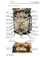
Page 81: ...information is primarily to furnish the repair engineer with a quick reference to the basic componentidentification and location A detailed breakdown of the equipment components and spare parts kits available can be found in Chapter 9 Spare Parts Figure 7 3 Main PCB Location 3Ph TL Control Logic PCB Part Nº 0SDE0072 Battery Charger PCB Part Nº 0SDE0074 Inverter Driver Feedback PCB Part Nº 0SDE0071...

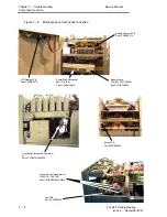
Page 82: ... Q1 Q2 Q3 Part Nº 0CATRCM150BU24F Transfer Diode 60A CD1 Part Nº 0CSDRFBYT261P12 Snubber Diodes 30A CD4 CD5 Part Nº 0CADR210230 Converter IGBT 200A Q4 Part Nº 0CATD212420 Input Bridge PD1 Part Nº 0CADTSSKD82 12 Input SCR 132A S7 Part Nº 0CSSX212413 Bypass SCR s 3 91A S2 S4 S6 Part Nº 0CASR212391 Transfer Diode 60A CD2 Part Nº 0CSDRFBYT261P12 Snubber Diode 30A CD3 Part Nº 0CADRFBYT231 Input SCR 132...

Page 83: ...0CPCPP4471200 Primary DC Bus Fuse 125A F1 Part Nº 0CEFXV412 Output Filter Caps x 6 60ìF C1 C2 C3 C4 C5 C6 Pt Nº 0CPCPA06600450 Capacitor 15ìF C7 Part Nº 0CPCPP615400 Capacitor 15ìF C8 Part Nº 0CPCPP615400 DC Bus Fuse 125A F3 Part Nº 0CEFXV412 Primary DC Bus Cap 15ìF C1 Part Nº 0CPCPP615400 Primary DC Bus Fuse 125A F4 Part Nº 0CEFXV412 Primary DC Bus Cap 15ìF C2 Part Nº 0CPCPP615400 Sec DC Bus Filt...

Page 84: ...attery Charger PCB Part Nº 0SDE0074 Fan PCB Part Nº 0SDE0078 Relay PCB Part Nº 0SDE0082 Battery Fuses 32A FS1 FS2 FS3 FS4 Part Nº 0CEFNC332 Power Circuit Breakers 63A I1 I2 I3 I4 Part Nº 0CESO4063 LCD Display PCB Part Nº 0SDE0075 Output Current Transformers 1 1000 TA1 TA2 TA3 Part Nº 0CEMC316610M019 Cooling Fan accessed from side VT1 Part Nº 0CEVTM2200800 ...

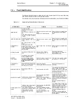
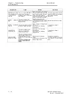
Page 85: ...discharge voltage This alarm is Normally seen during an extended Mains Failure Confirm the alarm is genuine by measuring the battery voltage If the alarm is not genuine replace the Auxiliary DC DC Converter STATIC SWITCH FAILURE Upon closing the Internal Static Switch one or more phases are missing at the UPS Output Check SCR of Bypass Check Bypass external connections Replace the faulty devices a...

Page 86: ...RY fused breaker and check Battery for open or short circuit cell Replace defective fuses or battery BATTERY CHARGER FAILURE This alarm is activated if a failure in the Battery Charger is detected Check integrity of Battery Fuses F1 F5 Check IGBT Q1 on the battery charger board Change battery charger if necessary HIGH BATTERY VOLTAGE LEVEL This alarm is activated by the detection of a High Battery...

Page 87: ...ED LD1 green ON UPS Normal OFF indicates an over temperature ST1 a DC offset condition or PCB power failure Auxiliary DCĆDC Converter SE0070 U2A pin 1 8 88V dc Battery voltage monitor R36 5 59V dc VMAX level adjustment P1 sets battery high level 500V R37 7 89V dc VMIN level adjustment P2 sets battery low level 320V R39 7 53V dc PREALARM level adjustment P3 350V Molex Connector PM2 Pin 1 16 83V dc ...

Page 88: ...em 4 Continue with any required fault diagnosis Table 7 3 Fuses Fuse Value Function Location F1 32A Battery Bank 1 F2 32A Battery Bank 2 Batte F e F o t S itch Pa el F3 32A Battery Bank 3 Battery Fuses Front Switch Panel F4 32A Battery Bank 4 F1 125A Primary DC bus ve U P S ti S Fi 7 5 F4 125A Primary DC bus ćve Upper Power Section See Figure 7Ć5 F2 125A Secondary DC bus ve U P S ti S Fi 7 5 F3 12...

Page 89: ...MMAND menu selection by pressing BACK and NEXT at the same time i e ENTER d Select the INVERTER ON OFF screen by pressing either the BACK C or NEXT B push button e Confirm INVERTER OFF function by pressing BACK and NEXT at the same time D A CONFIRMED message will be displayed f Press CLEAR twice to return at the main screen 4 The follow sequence should occur a The Alarm buzzer is activated b the R...

Page 90: ...ross F1 and F4 has fallen less than 20V dc The UPS is now safe to carry out further investigation Note The half DC bus level can also be monitored if required by connecting the DVM across the ve or Ćve fuse and the DC common neutral bus bar as shown in Figure 7Ć7 Figure 7 7 DC Bus Voltage check F2 F3 Check Secondary DC bus between Fuse F3 F2 765V DC To Check Half Secondary DC bus Voltage check for...

Page 91: ...guish The UPS will remain on bypass until the alarm condition is reset using the Reset push switch S1 on the PCB or the UPS is completely powered down and restarted Figure 7 9 Typical output current waveforms with DC offset 0 0 0 Normal output current waveform Output current waveform showing DC Offset Effect on the Output current waveform with unbalanced non linear load DC Offset DC Offset DC Offs...

Page 92: ...asure the DC offset level with the load connected if it is out of limits then the problem is load related b Check again with no load if the DC offset level is out of limits then the problem may lie with the UPS 4 If the DC Offset appears to be generated by the UPS check the voltage across D94 and D89 on the inverter driver feedback PCB Part Nº OSDE0071 The voltage should be equal 5 If an unequal v...

Page 93: ...t unnecessary strain being applied to the device substrate 7 Use the tightening sequence shown in Figure 7Ć10 Figure 7 11 Screw tightening sequence 1 2 3 4 8 Finally tighten the screws to the appropriate torque shown in Table 7Ć4 Ci it R f P t Nº Pan head Torque Nm Circuit Ref Part Nº Pan head Sems Heatsink Terminal Bridge PD1 0CADTSSKD82 12 M4 X 12FL 2 2 Diode CD1 CD2 0CSDRFBYT261P12 3 5 3 5 Diod...

Page 94: ...ne 2 Gain access to the UPS power section by removing the top and side covers 3 Disconnect and remove the Inverter driver feedback PCB Part NºOSDE0071 Follow the procedure on page 7Ć32 4 Remove the converter bus bar retaining screws from IGBT Terminal 2 and 4 5 Remove capacitors C9 and C10 from the bus bars 6 Remover the connecting screws from diodes CD4 and CD5 7 Remove the bus bar retaining scre...

Page 95: ... as the external voltage source Hinet Third Generation IGBT s Circuit Ref IGBT Type Liebert Hiross Part Nº IGBT Q1 Q2 Q3 EUPEC BSM150GB120DN2 Twin 0CATR210415 IGBT Q4 EUPEC BSM200GA120DN2 6 Single 0CATD212420 Table 7 8 Third generation IGBT usage Testing the IGBT 1 Power down the UPS and gain access to the power sections by following the procedure on page 7Ć3 2 Ensure that the power sections have ...

Page 96: ... leads ć ć 0 345 Turn off the device by shorting B2 G2 and E2 1 1 2 Ć 7 2 Ć 5 OL High resistance indicates the IGBT is off Note Terminal connections for single pack IGBT are shown in square brackets Testing the second IGBT Connect DVM across the emitter cathode junction 3 1 OL IGBT switched off a serviceable condition Reverse DVM leads to check internal diode 1 3 0 336 Diode forward resistance ReĆ...

Page 97: ...Service Manual Test Procedures 7 21 3x3 UPS Issue 2 November 2001 Figure 7 12 IGBT internal circuit and external connections Twin pack IGBT Part Nº OCATR210415 Single pack IGBT Part Nº OCATD212420 ...

Page 98: ...ge of 10 to 20 ohms for a serviceable SCR a high resistance would indicate an open circuit It is therefore recommended that a functional test of the SCR is carried out using the simple test circuits shown in Figure 7Ć12 and Figure 7Ć14 Twin Pack SCR Replacement S1 S2 S3 S4 S5 S6 1 Power down the UPS and carry out the DC bus discharge routine 2 Gain access to the UPS power section by removing the t...

Page 99: ...ttery and 12V bulb 1 Connect the bulb and battery to SCR1 as shown connect the ve to the anode 1 and ćve to the cathode 2 terminal 2 Using a second power source or link from the battery connect the ve lead to SCR1 gate terminal 4 and the ćve lead gate terminal 5 3 Switch on the SCR by briefly making the gate circuit use a switch if available The SCR will fire and the bulb will light and remain on ...

Page 100: ...12 SCR 1 and F11 SCR 2 on the Inverter driver feedback PCB Note There is no connection to SCR terminal 3 9 Remove the two SCR Allen retaining screws from the SCR and lift from the Heatsink Note There is a deĆcoupling capacitor linking the heatsink from SCR mounting screw to the neutral bus bar SCR S8 10 Disconnectthe battery ve cable from SCR terminal 3 11 Disconnect red leads from R1 to SCR termi...

Page 101: ...power source or link from the battery connect the ve lead to the SCR gate terminal 4 and the ćve lead gate terminal 5 3 Switch on the SCR by briefly making the gate circuit use a switch if available The SCR will fire and the bulb will light and remain on The bulb provides a current source for the SCR and it will continue to fire 4 Remove the ve connection from terminal 1 The bulb will extinguish a...

Page 102: ...the Auxiliary Converter PCB Connect the Negative to the rearmost pin and positive to the front most pin 9 Close links J5 J4 on the Control Logic PCB Part Nº OSDE0072 10 Fit a wire link from Test Point TP30 to capacitor C30 side nearest to IC U12 on the Control Logic PCB This forces a mains OK signal 11 Close the selected battery fuse 12 Wait for the UPS to initialise 13 Press the inverter ONĆOFF p...

Page 103: ...ohmmeter between the capacitor terminals and verify that the capacitor charges up eventually the meter will indicate OL b Measure the resistance between each capacitor terminal and ground capacitor body earth ć this should indicate open circuit in each case 6 Replace any capacitor that fails the above checks Capacitor open circuit checks 1 Transfer the load to the Maintenance Bypass supply 2 Total...

Page 104: ...own the UPS and carry out the DC bus discharge routine 2 Gain access to the UPS power section by removing the top and side covers 3 Mark all connectors before removal 4 Disconnect Connector PM1 and PM2 5 Release the PCB StandĆOff mounts and remover the PCB from the Unit Replacing the PCB 1 Replace the DC Ć DC converter PCB using the opposite sequence to the removal All replacement PCB s leave the ...

Page 105: ...and remove the PCB from the unit Replacing the PCB 1 Replace the UPS Monitor Board using the opposite sequence to the removal All replacement PCB s leave the manufacturer pre calibrated therefore no adjustment should be necessary 2 When fitting a replacement PCB the on board links must be checked to ensure they are in the correct position Link and Jumper functions Link Position Function JP1 1 2 cl...

Page 106: ... Mark all connectors before removal 4 Disconnect connectors J19 J15 and J7 5 Disconnect SCR driver connectors J1 to J6 6 Disconnect the inverter IGBT gate drive connectors J9 J11 and J12 7 Disconnect the converter IGBT gate drive lead J14 8 Disconnect the input SCR gate drive connector J16 9 Disconnect connectors J8 J10 J13 and J18 10 Disconnect J21 Note J21 connector leaves the two rear pins free...

Page 107: ...to the removal All replacement PCB s leave the manufacturer pre calibrated therefore no adjustment should be necessary 2 When fitting a replacement PCB the on board links must be checked to ensure they are in the correct position Link and Jumper functions a J4AĆJ5A sets the DC Bus voltage DC V Link J4A J5A 375V service maintenance mode close close 750V normal operation open open b JIAĆJ2AĆJ3A sets...

Page 108: ...ication 10kVA 0SDE0072 10 QSR 10 15kVA 0SDE0072 15 QSR 15 20kVA 0SDE0072 20 QSR 20 30kVA 0SDE0072 30 QSR 30 1 Power down the UPS and carry out the DC bus discharge routine 2 Gain access to the UPS power section by removing the top and side covers 3 Mark all connectors before removal 4 Note the position of the shorting links fitted to the PCB 5 Disconnect connectors CN2 CN4 and CN5 6 Release the PC...

Page 109: ... close J8 close close open d J9ĆJ10ĆJ12 defines the inverter peak current limit for the appropriate UPS output rating Link 10K 20K 30K J9 open close open J10 open open close J12 open open open e J11 define the converter peak current limit normally closed for all UPS output ratings 3 Carry out the Inverter and Converter functional test outlined on page 7 15 Potentiometer adjustment 4 It is unlikely...

Page 110: ...dling the PCB 4 With a DVM check for a voltage across F4 and F5 C1 and C9 5 If a voltage is detected discharge the capacitors using a 1kÙ 4Watt Resistor or equivalent Connect the discharge resistor to the voltage test point Across F4 F5 C1 and C9 6 Mark all connectors before removal 7 Disconnect connectors CN1 CN2 and CN3 8 Remove the ftwo Heatsink securing bolts 9 Carefully lift the complete PCB ...

Page 111: ...JP5 to JPI0 set the capacity for the installed battery this is used for the battery test function Link JP10 JP9 JP8 JP7 JP6 JP5 7 2Ah 2 x 7 2Ah 3 x 7 2Ah 4 x 7 2Ah 38Ah 65Ah e JP11 when selected open inhibits the battery test regime Note JP11 JP12 and JP13 are always set closed f J4ĆJ5ĆJ6 set the automatic battery test interval Link J4 J5 J6 Time 12 Hours 24 Hours 48 Hours Battery Charger Voltage ...

Page 112: ...op and side covers 3 Mark filter wiring before disconnection 4 Remove the five retaining terminal screws and disconnect the filter wires a Red wire from PW3 PHĆR b Black wire from PW4 PHĆS c Brown wire from PW5 PHĆT d Blue wire from PW2 Neutral 5 Carefully lift the PCB from the unit Replacing the PCB 1 Replace the Input Filter PCB using the opposite sequence to the removal 2 Refit all covers remov...

Page 113: ...r 3 Mark all connectors before removal 4 Disconnect connectors CN1 and J1 5 Remove the Left and Right hand fixing bolts in order to remove the assembly Replacing the Assembly 1 Replacing the Operator Control Panel assembly is the oppoite sequence to the removal Adjusting the LCD contrast If required the contrast of the LCD can be adjusted using the potentiometer P1 on the rear of the Operator Cont...

Page 114: ......

Page 115: ...ansformer 15kVA ISOLTX15 Isolation Transformer 20kVA ISOLTX20 Isolation Transformer 30kVA in Cabinet ISOLTX30 Remote Panel 8 1 Second Relay card Optional A Relay card is supplied upon customer demand The Relay card functions are the same as the standard card but the second relay card option provides a tag block allowing the duplication of the same signals as the DB9 plug Therefore any type of devi...

Page 116: ...to 30kVA by changing some internal components Note This upgrade must be carried out by a qualified ĆTrained Engineer Additional components may be required Batteries Circuit Breakers etc depending on the actual inĆ stallation unit configuration 8 4 Isolation Transformer The isolation transformer is a starĆstar configuration and can be connected either in the input or output side This item must be f...

Page 117: ...200 V 0SDE0082 Relay Board 0SDE0070 Auxiliary Converter Board 0SDE0071 Driver Feedback Interface 0SDE0072 10 Control Logic Board 10KVA 0SDE0072 15 Control Logic Board 15KVA 0SDE0072 20 Control Logic Board 20KVA 0SDE0072 30 Control Logic Board 30KVA 0SDE0077 UPS Monitor Board 0SDE1074 Battery Charger Assembly 0SDE0075 LCD display 0SDE0078 Fan Board 0SDE0079 Input filter 0SDE0080 EMC RF Filter Board...

Reviews: