Service Manual
Test Procedures
7 - 16
3x3 UPS
Issue 2 - November 2001
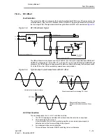
Action
1.
To determine if the DC offset problem is load related.
Replace the normal load temporarily with a resistive load and monitor the alarm condition, if
it disappears then the problem lies with the load.
2.
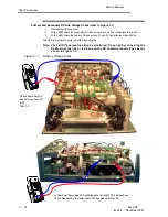
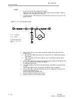
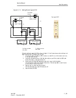
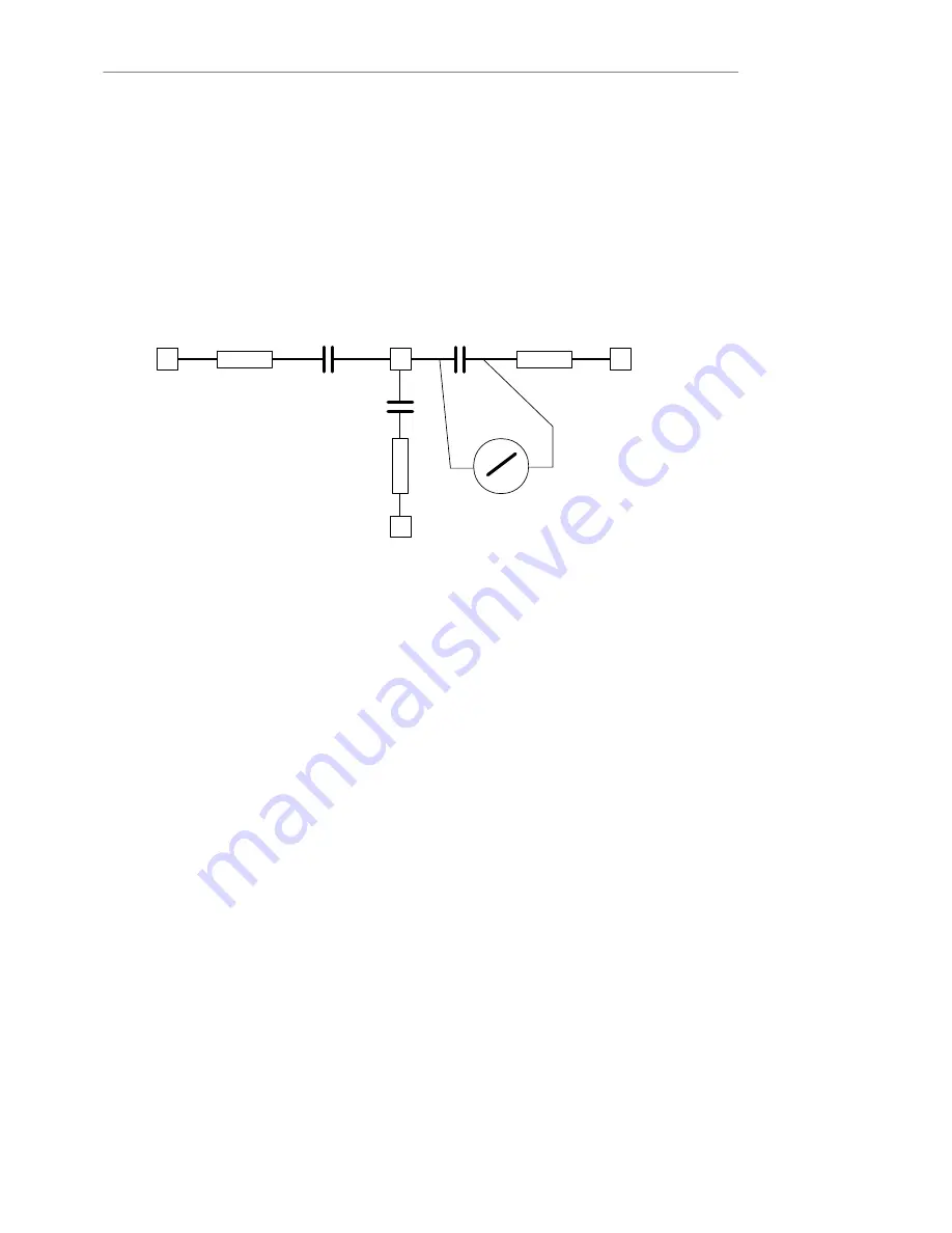
To measure the level of DC offset present, connect the test circuit shown in Figure 7Ć9 to the
output of the UPS.
Figure 7-10 DC offset test circuit.
V3
U3
W3
N3
R1
R1
R1
C1
C3
C2
Meter
All R = 120k
Ù
2Watt
All C = 1
ì
F 250V
DC checked across each
capacitor normal level
50mV
3.
Measure the DC mV across each phase capacitor the nominal level should be 50mV the
maximum 400mV.
a)
Measure the DC offset level with the load connected if it is out of limits then the problem
is load related.
b)
Check again with no load if the DC offset level is out of limits then the problem may lie
with the UPS.
4.
If the DC Offset appears to be generated by the UPS, check the voltage across D94 and D89
on the inverter driver/feedback PCB Part Nº OSDE0071.
The voltage should be equal.
5.
If an unequal voltage is measured then the fault is likely to be in either the inverter gate drive
or IGBT's.
Check that the IGBT drive circuit is correct and the IGBT devices are serviceable.
6.
If the circuit and IGBT checks are OK the problem points to a defective monitoring circuit in
the inverter driver/feedback PCB.
Replace the inverter driver/feedback PCB.
7.
Reconnect all cables and fit any covers removed.
8.
Restore the UPS to its normal running condition.


