Service Manual
Test Procedures
7 - 19
3x3 UPS
Issue 2 - November 2001
7.8.4 - IGBT testing
Two types of IGBT are used on the series UPS.
a)
Twin pack devices used in the inverter section.
b)
A single pack devices used on the converter.
All the devices currently used on the , are the latest `advanced second' or `third' generation type,
these have a higher gate emitter impedance. Difficulty can be experienced testing this type of IGBT
using a standard DVM, as they lack the battery power to switch on the device.
This difficulty can give rise to an incorrect diagnosis and a perfectly serviceable IGBT may be marked
as defective.
As a normal DVM cannot produce a high enough voltage to switch on a advanced second or third generĆ
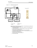
ation IGBT, it is recommended that the functional test is carried out with the use of an external dc power
supply.
Note: A 9V PP3 battery can successfully be used as the external voltage source.
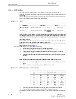
Hinet Third Generation IGBT's
Circuit Ref.
IGBT Type
Liebert Hiross Part Nº
IGBT Q1, Q2, Q3
EUPEC BSM150GB120DN2
Twin
0CATR210415
IGBT Q4
EUPEC BSM200GA120DN2 (6)
Single
0CATD212420
Table 7-8
Third generation IGBT usage
Testing the IGBT
1.
Power down the UPS and gain access to the power sections by following the procedure on
page 7Ć3.
2.
Ensure that the power sections have been completely isolated, check using a DVM.
3.
Locate the IGBT to be tested and totally isolate it by disconnecting its gate drive lead from
the inverter drivers and feedback PCB, and the power leads from the screwed terminals.
4.
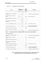
Test the IGBT using a DVM and a 9V dc power source.
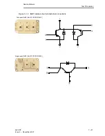
Follow the procedure shown in Table 7Ć6. Refer to Figure 7Ć11 for the IGBT internal circuit.
5.
Replace the IGBT if required.
Ensure the correct fitting procedure is used. Refer to Table 7Ć4 for correct torque values.
6.
Reconnect the IGBT gate drive and power connections.
7.
Carry out a test of the Inverter or Converter.
8.
Replace all panels removed and restore the UPS to its normal working condition.


