Service Manual
Test Procedures
7 - 20
3x3 UPS
Issue 2 - November 2001
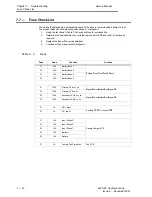
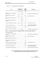
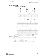
Table 7-9
Functional check of power IGBT's
Action
DVM/Battery Lead
Connection
DVM
Indication
(mV)
Interpretation
+ve to:
Ćve to:
IGBT
Connect DVM across the emitter cathode
junction.
1
[1]
2 Ć 7
[2 Ć 5]
OL
IGBT switched off a serviceable condition.
Reverse DVM leads to check internal
diode.
2 Ć 7
[2 Ć 5]
1
[1]
0.355
Diode forward resistance.
ReĆconnect DVM leads across emitter cathĆ
ode.
1
[1]
2 Ć 7
[2 Ć 5]
OL
Connect the 9V power supply (battery)
negative Ćve
2 Ć 7
[2 Ć 5]
OL
Touch the +ve Battery lead to gate (base).
6
[3]
2 Ć 7
[2 Ć 5]
0.345
This will switch on the device.
ReĆcheck the emitter cathode junction.
1
[1]
2 Ć 7
[2 Ć 5]
0.345
Low mV reading indicates IGBT has
switched on and is serviceable.
Disconnect the bve and Ćve leads.
ć
ć
0.345
Turn off the device by shorting B2(G2) and
E2.
1
[1]
2 Ć 7
[2 Ć 5]
OL
High resistance indicates the IGBT is off.
Note:
Terminal connections for single pack IGBT are shown in [square brackets]
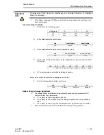
Testing the second IGBT
Connect DVM across the emitter cathode
junction.
3
1
OL
IGBT switched off a serviceable condition.
Reverse DVM leads to check internal
diode.
1
3
0.336
Diode forward resistance.
ReĆconnect DVM leads across emitter cathĆ
ode.
3
1
OL
Connect the 9V power supply (battery)
negative Ćve
1
OL
Touch the +ve Battery lead to gate (base).
4
1
0.345
This will switch on the device.
Disconnect the bve and Ćve leads.
ć
ć
0.345
ReĆcheck the emitter cathode junction.
3
1
0.345
Low mV reading indicates IGBT has
switched on and is serviceable.
Turn off the device by shorting B1 and E1.
3
1
OL
High resistance indicates the IGBT is off
Note: The DVM readings shown in the above table are typical they will vary
slightly from device to device and with the type of meter used.


