Powertronix spa reserves the right to modify this document without notice
Page 38 of 46
R&D – USER MANUAL DT0430-E04
4.5. INSTRUCTION FOR SYSTEM START-UP IN “NORMAL” MODE
(Optonal configuration)
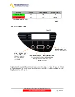
For the switches details refer to the fig. 4.3
1. Close the INPUT RESERVE (l2) switch
The LCD panel and all UPS logic boards will begin normal operation.
If the reserve line voltage parameters are correct, the UPS fans will switch on.
On the control panel the red indicator will appear.
2. Close the UPS OUTPUT (l4) switch
The load connected to the UPS output will be supplied with the power provided by the reserve line.
On the control panel the red indicator remains on.
3. Close the MAINS INPUT (l1) switch
After 5 seconds the automatic start-up procedure will be started and the LCD display will show
”Autostart process activated” message, and later - the percentage of process advance.
At the process end UPS will show message: ”Autostart process finished” and on the control panel the
red indicator will remain on.
In the event of anomaly on LCD displays the message “Autostart process failed” and on the control
panel the red indicator remains on. In this situation don’t proceed with the start-up and call the service.
4. Battery connection
After checking the correct polarity of the batteries close the battery panel switch on battery cabinet. It
makes the connection between the batteries and the UPS circuits.
5. Switch on the inverter
To complete the start-up procedure, enter into “3. UPS COMMANDS” of the menu, choose and
confirm “3.1 SYSTEM START”. The inverter will be activated and after 20 seconds automatically
switch the load on it (if the UPS is configured to POWER SAVE, the load remains on reserve line).
At the end of procedure on the LCD panel displays the message “Autostart process finished” and the
green indicator on the control panel will appear.
The system makes an automatic battery test 2 minutes after the message
”AUTOSTART PROCESS
FINISHED” is shown on the display LCD. In case of anomaly an alarm message “BATTERY TEST
FAILED” will be displayed and the red light on the control panel will remain on; in this situation
check the battery voltage and connection then execute a manual battery test again (as described in
a chapter 3.2.4)
At this point the unit is in normal operating mode, and guarantees uninterrupted power supply to the load.
It is suggested to simulate the short power failure to check the correct operation of the entire UPS / battery
system. To perform this operation just open and then close the mains switch powering the UPS.


