R&D – TECHNICAL SPECIFICATION DT0424-E01
Powertronix spa reserves the right to modify this document without notice
Page
.
19 of 73
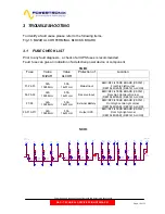
3.2 POWER
FUSE
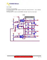
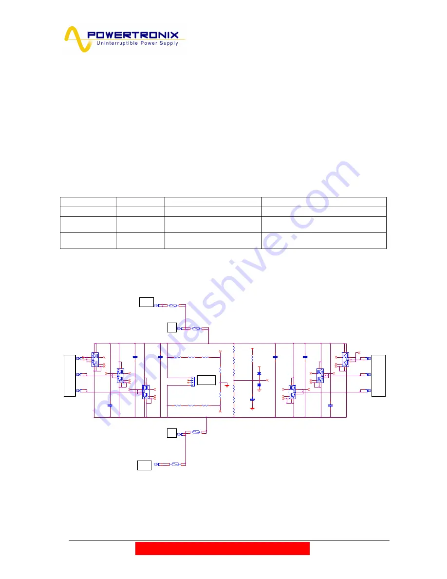
F1-F2: Positive and Negative DC BUS.
F3-F4: Positive and Negative BATTERY
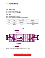
3.2.1 Mizar
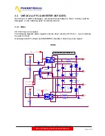
Refer to Electrical Diagram :DE0152
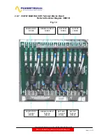
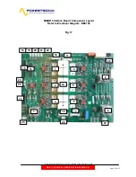
Refer to Fig.8 MIZAR Interface Board Component Layout
TAB.2
Fuse Value Protection
of
Location
F1-F2
32A
10x38mm
Battery Input
Power Interface BOARD (DE0152)
MIZAR
F3-F4
32A
10x38mm
DC BUS
Power Interface BOARD (DE0152)
MIZAR
SCH.2
P+5
P+5
E1-T
16_+DC-BUS
G3-T
E4-B
G1-T
G4-T
E5-B
G5-T
G2-B
E3-B
G6-B
G4-B
G1-B
E3-T
E6-T
REF
16_-DC-BUS
G3-B
E5-T
G6-T
E2-B
G2-T
E6-B
G5-B
E4-T
E1-B
E2-T
AUX_CONV -DC
AUDC
FS6
L1
FS5
L2
FS22
L3
R183
100K 0.25W
R184
100K 0.25W
Q3
SK60GB128
28
6
13
27
2
1
24
12
5
23
F2
32A 10x38
1
2
3
4
C37
2.2µF PHB
850V
2
1
FS21
L2
Q6
SK60GB128
28
6
13
27
2
1
24
12
5
23
R180
150K 0.25W
R186
100K 0.25W
FS14
+ DC
R181
150K 0.25W
R188
150K 0.25W
C38
2.2µF PHB
850V
2
1
Q2
SK60GB128
28
6
13
27
2
1
24
12
5
23
C43
2.2µF PHB
850V
2
1
Q4
SK60GB128
28
6
13
27
2
1
24
12
5
23
R96
150K 0.25W
C40
2.2µF PHB
850V
2
1
R97
150K 0.25W
FS4
L3
C41
2.2µF PHB
850V
2
1
D42
1N4148
2
1
+
C62
10µF 16V
R187
100K 0.25W
F3
32A 10x38
1
2
3
4
Q1
SK60GB128
28
6
13
27
2
1
24
12
5
23
F1
32A 10x38
1
2
3
4
FS15
-DC
R185
100K 0.25W
F4
32A 10x38
1
2
3
4
D41
1N4148
2
1
R98
150K 0.25W
R99
6.8K
R100
6.8K
FS20
L1
R182
100K 0.25W
FS11
- BATTERY
R95
150K 0.25W
Q5
SK60GB128
28
6
13
27
2
1
24
12
5
23
FS10
+ BATTERY
CN3
DC BUS
1
2
3
4
C39
2.2µF PHB
850V
2
1
F
rom
I
n
pu
t
Indu
c
tor
To Aux.
Conve rte r
CS0153
OUTPUT INVERTER
To Inverter
Inductor
INPUT INVERTER
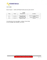
Note the location of fuse are different in Mizar compare to Alcor:


