R&D – TECHNICAL SPECIFICATION DT0424-E01
Powertronix spa reserves the right to modify this document without notice
Page
.
21 of 73
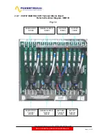
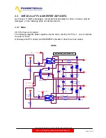
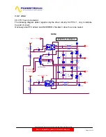
3.3 CHECK ALL PFC & INVERTER OUT IGBTS.
well locked . If IGBT is damaged , remember that probably the driver circuitry could be
damaged , so the following parts on interface board.
3.3.1 Mizar
CS 0152 have to be tested.
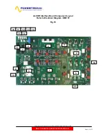
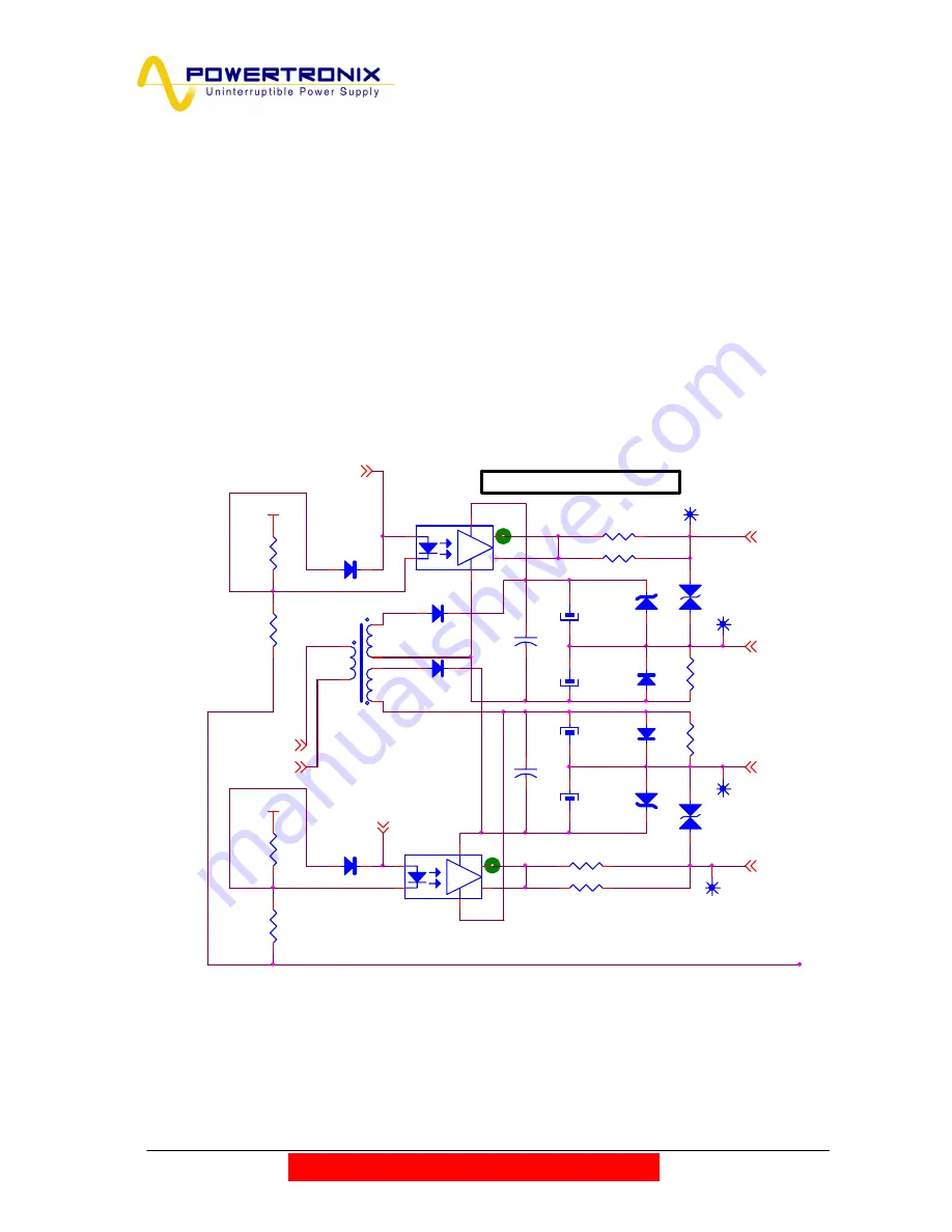
The following diagram detail regards only the driver circuitry for PFC L1 , only to indicate
the part of circuit .
Obviously also PFC L2&L3 and INVERTER L1&L2&L3 driver has to be tested.
SCH.3
P+15
P+15
HF supply 1
HF supply 2
DRV_L1-TOP_ING
DRV_L1-BOTT_ING
G1-T
E1-T
G1-B
E1-B
R4
1.8K
R10
270
R28
270
R19
1.8K
D4
UF4007
2
1
Z4
15V
2
1
+
C7
10
0µ
F
3
5
V
TP1
D10 1N4148
2
1
T1
VAC4721X004
1
6
3
2
4
5
+
C1
10
0µ
F
3
5
V
D13
1N4148
2
1
+
C16
10
0µ
F
3
5
V
+
-
Totem
ISO4
HCPL3120
2
3
6
5
8
7
R13
1K
+
C10
10
0µ
F
3
5
V
+
-
Totem
ISO1
HCPL3120
2
3
6
5
8
7
TP10
R22
33
Z10
P6KE18C
AC
250
2
1
R7
33
C4
1µF
D1
1N4148
2
1
Z1
P6KE18C
AC
250
2
1
D7
UF4007
2
1
TP4
Z7
15V
2
1
R16
1K
R1
33
TP7
R25
33
D16
1N4148
2
1
C13
1µF
INVERTER_IN PHASE L1


