R&D – TECHNICAL SPECIFICATION DT0424-E01
Powertronix spa reserves the right to modify this document without notice
Page
.
27 of 73
3.5.2 Check Control Board
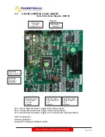
If at least one of the source input are available (reserve/Mains/Battery)is possible to
check the control Logic board
3.5.3 Check Power Supply Voltage
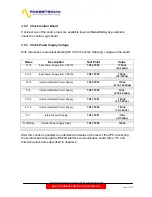
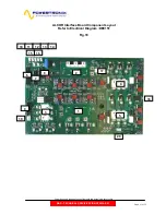
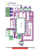
With references to electrical drawing DE 0150 check the following voltage-on the board
Name Description
Test
Point Value
P+15
Input Power Supply from CS0152
TP55-TP52 17.5Vdc
(15-20Vdc)
P+7.5
Input Power Supply from CS0152
TP61-TP58 7.5Vdc
(7.5-10Vdc)
P+12
Internal stabilized Power Supply
TP55-TP53 12Vdc
(11.75-12.25Vdc)
P+5
Internal stabilized Power Supply
TP61-TP59 5Vdc
(4.75-5.25Vdc)
P+3.3
Internal stabilized Power Supply
TP61-TP63 3.3Vdc
(3.1-3.5Vdc)
P+1.5
Internal stabilized Power Supply
TP61-TP64 1.5Vdc
(1.4-1.6Vdc)
N-7
Internal Power Supply
TP61-TP67 -7Vdc
(-6/-10Vdc)
P+12Delay
Internal Power Supply Delay
TP61-TP54 12Vdc
After this control is possible to understand the status of the rest of the UPS connecting
the control board through the RS232 interface communication board with a PC and
follow the procedures described in chapter 4.


