R&D – SERVICE MANUAL DT0488
Powertronix spa reserves the right to modify this document without notice
Page
.
24 of 72
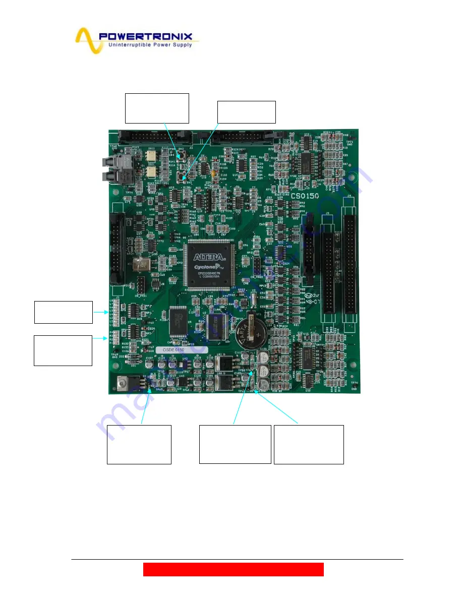
CS0150 CONTROL LOGIC BOARD
Refer to Electrical Diagram :DE0150
Fig. 16
DL1= Green ON when Power supply 5Volt Volt is present
DL2= Yellow ON when Power supply 12Volt Volt is present
DL3= Green ON when Power supply 12 Volt is inside the right parameters
SW1=Push Button
SW2=Push Button
Upload STL Software Enable Function
LED BAR
UPS STATUS
LED BAR
Processor
STATUS
SW1-Button
Not Used
SW2-Button
Up-load
software micro
LED DL1-Green
Power 5
Volt
Enabled
LED DL2-Yellow
Power 12
Volt
Enabled
LED DL3-Green
Power Supply
+12 Volt
Enabled


