R&D – SERVICE MANUAL DT0488
Powertronix spa reserves the right to modify this document without notice
Page
.
27 of 72
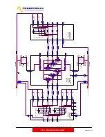
3.3 POWER INTERFACE UPS-10-15KVA BOARD
On this board are present all the electrical circuit used to adapt the level to the real used
from control, and all the actuators circuit used to drive the power parts present on UPS :
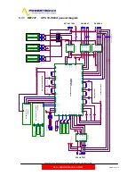
Here are described all the main component present on board (look figure 17 in the next
page):
Description N°
Ref.
Drawing
IGBT –L1 Input PFC
1
DE0152-Pag.2
IGBT –L2 Input PFC
2
DE0152-Pag.2
IGBT –L3 Input PFC
3
DE0152-Pag.2
IGBT –L1 Output INV
4
DE0152-Pag.2
IGBT –L2 Output INV
5
DE0152-Pag.2
IGBT –L3 Output INV
6
DE0152-Pag.2
Pre-charge Input section RELE
7
DE0152-Pag.2
SS-Switch Inverter Relay
8
DE0152-Pag.3
SS-Switch
Reserve
Relay
9
DE0152-Pag.3
Positive Battery Fuse Protection
10
DE0152-Pag.2
Positive DC Capacitors Fuse
11
DE0152-Pag.2
Negative DC Capacitors Fuse
12
DE0152-Pag.2
Negative Battery Fuse Protection
13
DE0152-Pag.2
Snubber
Capacitors
14
DE0152-Pag.2
J4 50-pin Flat Cable Connector to Control Logic CS 0150
15
DE0152-Pag.4
J5 40-pin Flat Cable Connector to Control Logic CS 0150
16
DE0152-Pag.4
J7 20-pin Flat Cable Connector to Auxiliary Power Supply CS 0153
17
DE0152-Pag.4
CN9 2-Pin Molex Connector to Thermal Sensor “°C External Battery Box”
18
DE0152-Pag.4
CN7 2-Pin Molex Connector to Thermal Sensor “°C Internal Battery Box”
19
DE0152-Pag.4
CN6 2-Pin Molex Connector to Thermal Sensor “°C Heatsink”
20
DE0152-Pag.4
CN5 2-Pin Molex Connector “Not used”
21
DE0152-Pag.4
CN1 2-Pin Molex Connector to Over Temperature Protection 85°C
22
DE0152-Pag.4
CN10 2-Pin Molex Connector to “AUX Contact MANUAL BYPASS”
23
DE0152-Pag.2
CN11 2-Pin Molex Connector “Not used”
24
DE0152-Pag.2
CN2 5-Pin Molex Connector “Mains line to CS 0153”
25
DE0152-Pag.2
CN3 4-Pin Molex Connector “Feedback DC-BUS Voltage”
26
DE0152-Pag.2
CN4 5-Pin Molex Connector “Reserve line to CS 0153”
27
DE0152-Pag.3
F42 1A 250V Fuse protection for Fan
28
DE0152-Pag.2


