background image

24

iv 
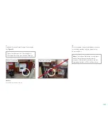
Provide a load from the house(turn on the Kettle) 
to confirm the Powervault is operating properly.  
If it is sunny outside(assuming a solar PV system  
is installed) the Powervault should change from 
green to pale blue or green to dark blue or dark 
blue to pale blue and back once the load is turned 
off. This will confirm the Powervault is operating 
properly.


After an hour or two take a look on the portal and see 
that the unit LED state matches what has been 
recorded on the portal. 

vi 
(Optional) Set up Economy 7 times using the 
Economy 7 tabs if the customer is eligible for 
Economy 7.  These hours should be modified 
during the year to make sure energy produced 
matches the customers expectations.  

Summary of Contents for G200

Page 1: ...1 Cover G200 INSTALLATION MANUAL WINNER Innovator of the Year Solar Innovation of the Year ...

Page 2: ...Powervault G200 must only be undertaken by approved Powervault installers qualified electricians Batteries This equipment is heavy and contains potentially hazardous voltages that may cause personal injury if handled incorrectly This equipment mustbeinstalledand servicedonlybyqualifiedelectrical service personnel The batteries should be disposed of or recycled according to your local code of condu...

Page 3: ...ult co uk warranty Product List 2 0 2 5 4 0 6 0 3 0 0 2 0 2 5 4 0 6 0 3 0 0 2 0 2 5 4 0 6 0 3 0 4 0 2 0 2 5 4 0 6 0 3 0 4 0 2 0 2 5 4 0 6 0 3 0 4 0 2 0 2 5 4 0 6 0 3 0 4 0 2 0 2 5 4 0 6 0 3 0 4 0 Lithium ion Lead Acid Tubular Gel Lead Acid AGM Powervault overview 4 Part 1 Wiring 5 Part 2 Preparing the Powervault 8 Part 3 Emergency Power Socket 9 Part 4 Loading batteries Option A Lead Acid batterie...

Page 4: ...product purchased Accessory Box Current CT clamp Current clamp extension cable Battery connectors Powervault G200 User Manual Powervault G200 Technical Specification Powervault G200 Installation Manual Parts not included with your delivery 7A 10A fused spur fuse size dependent on Powervault type Rotary isolator Associated wiring Wi Fi nano router ...

Page 5: ...r type of connection may result in a shock hazard In order to maintain compliance with the EMC directive wires attached to the Powervault should not exceed 25 meters in length Preparetheelectricalwiringaccordingtofigure1orfigure2 Allwiringtobeperforminstrictaccordancewith localbuildingregulations TheidealinstallationwillfeatureaseparateRCBOblocksplittingfromtheHenleyBlockasshowninfigure1 Ifthisisn...

Page 6: ... Henley Block connection RCBO Consumer Unit Not included dedicated for Powervault Not included Additional power socket if required for nano router Rotary Isolator RCBO 7A 10A fused spur Powervault Wi Fi internet Household ring main Installation schematic Current clamp with arrow indication FIGURE1 Recommended Installation ...

Page 7: ...ot included dedicated for Powervault Not included Additional power socket if required for nano router Rotary Isolator 7A 10A fused spur Powervault Wi Fi internet Household ring main w Dedicated RCBO for the Powervault Current clamp Installation schematic FIGURE2 Possible Installation Check with local regulations Current clamp with arrow indication ...

Page 8: ...IAL DO NOT SCALE DRAWING REVISION TITLE DWG NO SCALE 1 20 SHEET 1 OF 5 A3 MATERIAL THICKNESS C Tyler A Locke 10 05 17 10 05 17 Dynamic Marine Engineering PV1_A00_8_Full 500 Assembly Full 500 Assembly 1 mm A A B B C C D D E E F F 8 8 7 7 6 6 5 5 4 4 3 3 2 2 1 1 DRAWN CHK D UNLESS OTHERWISE SPECIFIED DIMENSIONS ARE IN MILLIMETERS SURFACE FINISH TOLERANCES LINEAR 0 05 ANGULAR 0 5 FINISH DEBURR AND BR...

Page 9: ...ervault s Emergency Power Socket EPS is not fitted as standard and Installers are therefore occasionally required to fit this accessory to the Powervault if the customer has ordered it The EPS gives customers access to power available in the batteries during black outs the EPS will be able to power basic electrical appliances provided the batteries have energy stored in them at the time during eme...

Page 10: ... onto the two screws located above and beneath the EPS on the Powervault G200 casing See figure 9 iv Facing the front of the Powervault G200 locate the plastic cover for the EPS in the bottom right corner Remove the cap by pushing it firmly outwards from inside the unit See figure 8 A DETAIL A SCALE 2 5 A B C D E F 8 8 7 7 6 6 5 5 4 4 3 3 2 2 1 1 PV1_A01_8_500 Assembly with S FIGURE8 FIGURE9 A B C...

Page 11: ...ug the AC out power cable into the bottom of the inverter viii Reinstall right side earth wire to panel attach panel to unit and reinstall screws see if finished reinstall earth wire to top and reinstall screws ...

Page 12: ...r the terminals iii Remove screws from top tray to allow for 2nd row of batteries to slide in place Keep the screws in a safe place for re installation Option A Loading Lead Acid batteries Power Connection To Powervault Cables Supplied as Part of Accessory Box Connect Red to positive and Black to Negative Cables supplied as part of accessory box connect RED to positive and BLACK to negative Power ...

Page 13: ...he connections on top of each other Each connector should click into place This will be the case on each shelf A A B B C C D D E E F F 8 8 7 7 6 6 5 5 4 4 3 3 2 2 1 1 PV1_A00_8_Full 500 Assembly with Batteries A B C D E F 7 7 6 6 5 5 4 4 3 3 2 2 1 1 PV1_A00_8_Full 500 Assembly with Batteries FIGURE11 Battery installation for 3kWh 4kWh units FIGURE12 Battery installation for 4kWh units only Note Th...

Page 14: ... page of this manual It will be needed for registration later ii For the 4kWh unit place 2 batteries as shown in figure 13 One battery per shelf iii For the 6kWh unit place 3 batteries as shown in figure 14 Two batteries on the bottom shelf and one on top shelf Option B Loading Lithium ion cells A A B B C C D D E E F F 8 8 7 7 6 6 5 5 4 4 3 3 2 2 1 1 PV1_A00_8_Full 500 Assembly with Li Ion Batteri...

Page 15: ...See figure 15 v The 6kWh unit will require that the power leads be split into the two battery packs on the lower shelf See figure 16 Battery power cables Data cable connection 5 Digit Serial Number Required for commissioning of unit and connecting to the portal Data Jump Connection Part of Accessory Box Data connection Left side in Right side out Power connections to Powervault Part of Accessory B...

Page 16: ...es are connected into a battery which is why this is recommended for the top shelf and on the 4kWh unit Note If the data connection is not made with all of the batteries the Powervault will not function 5 Digit Serial Number Required for commissioning of unit and connecting to the portal Data Connection on right hand side of battery Power connection to Powervault Use both connectors for 1 battery ...

Page 17: ...S SURFACE FINISH TOLERANCES LINEAR 0 05 ANGULAR 0 5 FINISH NAME SIGNATURE DATE C Tyler A Locke 10 05 17 10 05 17 A A B B C C D D E E F F 8 8 7 7 6 6 5 5 4 4 3 3 2 2 1 1 DRAWN CHK D UNLESS OTHERWISE SPECIFIED DIMENSIONS ARE IN MILLIMETERS SURFACE FINISH TOLERANCES LINEAR 0 05 ANGULAR 0 5 FINISH DEBURR AND BREAK SHARP EDGES NAME SIGNATURE DATE MATERIAL DO NOT SCALE DRAWING REVISION TITLE DWG NO SCAL...

Page 18: ...nd any power wiring for a long run The cable can share a wall penetration but should then branch away from any power wiring to at least 10cm Do not install the current clamp cabling in same conduit as power cables due to interference see figure 22 FIGURE21 Powervault socket for current clamp ELECTRICAL SAFETY Ensure the Powervault G200 is completely isolated from the mains supply WALL WALL Current...

Page 19: ...rvault unit The current clamp wire is 10m in length A 10m extension lead is provided free of charge Note If installing a lithium ion unit the lights on the front will change colour after 20 seconds If the colour is red please contact Powervault or look at FAQs on the website FIGURE4 Correct installation Incorrect installation FIGURE23 Current clamp installation example ...

Page 20: ...be purchased configured and connected directly to the Powervault RJ45 port located on the back of the Powervault via ethernet cable not provided We recommend using one of four types of wireless nano routers TP link RE210 Wi fi extender with Ethernet output TP link PA4010KIT Powerline adapter kit Alternatively individual units can be purchased e g for 3 way networks Netgear WN3000RP Wi fi extender ...

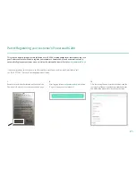
Page 21: ...Portal portal powervault co uk If you have forgotten your Username and Password to your Powervault Installer Portal please call 44 0 20 3773 8312 or email service powervault co uk i Record the serial number located on the back of the Powervault Record this number on the back page ii After logging into portal powervault co uk click on Register Powervault Installation iii Fill in form using the end ...

Page 22: ...l an email will be sent to the customer with login details vi The customer can now check their email for login information on portal powervault co uk to view the Powervault dashboard Note Theunitnumbercanbeclickedonin the Powervault portal but it may take up toanhour forthe unit tosend dataonline ...

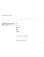
Page 23: ...erfectly normal state The device could be fully charged and the solar panels are exporting power to the grid The device batteries couldbeemptyandthehouseisimportingpowerfrom the grid If the colour of the lights are red or yellow please check the cabling connections to the batteries in Part 4 Please ensure that the unit is isolated prior to If this does not correct the light colour Green Charging D...

Page 24: ... blue to pale blue and back once the load is turned off This will confirm the Powervault is operating properly v After an hour or two take a look on the portal and see that the unit LED state matches what has been recorded on the portal vi Optional Set up Economy 7 times using the Economy 7 tabs if the customer is eligible for Economy 7 These hours should be modified during the year to make sure e...

Page 25: ...act Powervault Ltd 29 Shand Street London SE1 2ES t 44 0 20 3773 8312 e service powervault co uk www powervault co uk Edition 06 2017 Powervaultserialnumber Li Ionbattery1serialnumber Li Ionbattery2serialnumber Li Ionbattery3serialnumber ...

Reviews: