background image

63 

. +

%

d !

! ! #

# %

d

is is to disconnect Cca les for & S #nput 7 OutputD and C

 detection ca leD  

e pictures as  elo  are e/a ples of C+ac! positionD onl"  

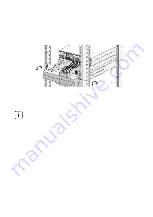
6  &nloc! t e clips and pull out 

 fro  its position s oot l", t en rotate t e 


as  elo


<  .isconnecting Cca les for & S #nput 7 OutputD and C

 detection ca leD as  ell as 

ot er ca les connected on & S  

3  +e o e out t e & S for ser ice or replace ent  

.onDt let t e 

 suffer an" strong stress during rotation position  

. -

%

% !  '

m

A) m d

larif" "our & S is alread" co plete ser ice or replace ent installation


6   onnect Cca les for & S #nput7 OutputD and C

 detection ca leD to & S ter inal 

---refer to c apter 3 B 

<   urn t e 

 C#nput s itc D to COND position  

e & S  ill turn to  "pass  ode  #f 

t e  & S  doesnDt  turn  to  "pass 

ode  auto aticall",  please  turn  to  "pass  ode 

anuall"  

3   +otate  t e 

aintenance  s itc   to  C& SD  position,  install  ac!  t e  C aintenance 

s itc  co erD to its nor al position  

B   ress t e  utton on & S 9 . panel, t e & S  ill turn to line  ode  

Summary of Contents for MBP 1-1

Page 1: ...PDU for VFI ICR IoT 6 10kVA Installation and user manual Service and support Call your local service representative ...

Page 2: ...thin 0 to 50 C free of conductive contaminant pecial s mbols H serve the warnin associated with the ris of electric shoc s m ol m ortant instructions that must alwa s e followed EU se arate collection mar for waste electrical and electronic equi ment WEEE ndicates that the item must not e dis osed of to the normal household waste ut e se aratel collected and rec cled nformation advice hel Refer to...

Page 3: ...vercurrent protection devices shall be provided by others for permanently connected AC input Normal AC Bypass AC and AC output circuits Check that the indications on the rating label correspond with your AC powered system and the actual electrical consumption of all the equipment to be connected to the system For PLUGGABLE EQUIPMENT the socket outlet shall be installed near the equipment and shall...

Page 4: ...cking and Inspecting 4 3 2 Checking the accessory kit 4 3 3 Mechanical Installation 5 3 4 Power cables connection 8 4 Service operation 12 4 1 How to switch system to BYPASS mode 12 4 2 How to disconnect cables between MBP and UPS 13 4 3 How to switch system to NORMAL mode 13 4 4 How to detect the EBM to this system 14 5 Specifications 15 ...

Page 5: ...ntal protection Products are developed according to an eco design approach Substances This product does not contain CFCs HCFCs or asbestos Packing To improve waste treatment and facilitate recycling separate the various packing components The cardboard we use comprises over 50 of recycled cardboard Sacks and bags are made of polyethylene Packing materials are recyclable Follow all local regulation...

Page 6: ...p 1 no programmable utput socket group programmable 3 utput reaker ptional default is no B aintenance bypass switch nput 7 utput terminal onnected to power and load 2 nput switch F nput 7 utput terminal onnected to 5 GB port including E Detect and T model 8ront anel roduct 0et Weights kg Dimensions mm W D PDU for VFI ICR IoT 6 10kVA 1 1 B B 2I5B I5 PDU for VFI ICRS IoT 10kVA 3 1 5 B 2I52 I5 ...

Page 7: ...1 utput socket group programmable aintenance bypass switch 3 nput 7 utput terminal onnected to power and load B nput switch GB port including E Detect and T model 2 nput 7 utput terminal onnected to 8ront anel ear anel ...

Page 8: ... and file a claim for shipping damage f you discover damage after acceptance file a claim for concealed damage ote4 Discard or recycle the packaging in a responsible manner or store it for future use acking materials must be disposed in compliance with all local regulations concerning waste ecycling symbols are printed on the packing materials to facilitate sorting 2 ec0i t e cce or 0it 4erify tha...

Page 9: ... detection ca leD to t e efore installing 6 e o e t e co er of ter inal loc s and connect Cca les for S nput7 OutputD to ter inal loc s refer to t e indication on rear panel 1 34 1 34 8or ca les ell fi ed it is reco ended to tie t ese ca les to t e con e of rear panel nstall ac t e co er of ter inal loc s and insert C detection ca leD ...

Page 10: ...o t e configured lengt of Cca les for S nput 7 OutputD and C detection ca leD 9eft position op position nstall C ar rac etD to t en asse le to S B scre s elo pictures are e a ples of C9eft positionD installation 0 4 is is fle i le position installing in a rac ca inet as elo t is reco ended to select C osition 6D as our final installation according to t e configured lengt of Cca les for S nput 7 Ou...

Page 11: ...F osition 6 ear of rac osition 8ront of rac 6 nstall C ail itD to rac ca inet scre s and as ers ...

Page 12: ...Slide into Crail itD and a e sure loc t e clips is c apter introduces o to connect to S and connect N7O ca le to 5 efore po er ca les connected nsert C detection ca leD to t e port C 7 D on t e rear of S ...

Page 13: ...o ended ca le ini u cross sectional area odel 6 6 3 6 Wit 2K S 6 6 Wit 60K S 6 6 Wit 60K S 3 6 rotecti e eart ing conductor 60 60 60 nput 9 N ca le 2 60 60 Output 9 N ca le 2 60 60 e lengt of t e output ca le is reco ended not to e ceed 60 eters ot er ise it a cause radio interference f a lengt of output ca le o er 60 eters requests please contact distri utors7 agents for details ...

Page 14: ...pe of connection ust e carried out qualified electrical personnel efore carr ing out an connection c ec t at t e upstrea protection de ices Nor al source are open LOL Off 6 e o e t e co er of ter inal loc onnect t e ca le to ter inal loc s refer to t e indication on panel 1 34 ...

Page 15: ...s elo default is setting it 3 6 ode 6 6 ode S ort C input ter inal 9679 793D it C us arD t en connect ca le 3 6 ode 8or ca les ell fi ed it is reco ended to tie t ese ca les to t e con e of rear panel 3 nstall ac t e co er of ter inal loc ...

Page 16: ... e S ill turn to pass ode auto aticall otate t e aintenance s itc to CD A SSD position Note1 8or an unconscious operation it is reco ended to install ac t e C aintenance s itc co erD as a o e to pre ent M A SSD s itc ac to C S odeD 3 urn t e Cinput s itc D to CO88D position B fter t ese operations t e ill po er t e load directl ia aintenance s itc ...

Page 17: ...place ent onDt let t e suffer an strong stress during rotation position m A m d larif our S is alread co plete ser ice or replace ent installation 6 onnect Cca les for S nput7 OutputD and C detection ca leD to S ter inal refer to c apter 3 B urn t e C nput s itc D to COND position e S ill turn to pass ode f t e S doesnDt turn to pass ode auto aticall please turn to pass ode anuall 3 otate t e aint...

Page 18: ...6B d E m is is to connect t e Cconfigured D to a s ste S it C detection ca leD as elo ...

Page 19: ...al a s on default Once it is set as auto off on t at output po er ill turn off en atter capacit elo 0 in atter ode and outlet soc et group rogra a le ill turn on again en c arger egins to or 3 n iron ent Operating te perature 0 B0 full load B0 0 derating to 0 0 3 soc et 62 3 B0 soc et 60 Storage te perature to 20 ransit te perature to elati e u idit 0 to 9 no condensing Operating altitude 3000 era...

Reviews: