33
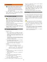
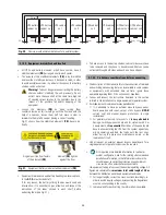
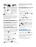
The label will bear the following or an equivalent text:
Before working on this circuit.
Isolate the Uninterruptible Power System (UPS).
Check the voltage between all terminals, including the
protective earth.
Risk of UPS backfeed voltage.
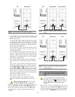
• Connect the bypass input cables to the respective terminals
according to the available equipment setting.
For parallel systems, it will be needed to repeat the connections
that go from panel board to each equipment.
Connection to three phase bypass mains
:
Connect the power supply cables R-S-T-N to the bypass
terminals
(X14)
,
(X15)
,
(X16)
and
(X17), respecting the
phase rotation and neutral
indicated on the label of the
equipment and in this manual. If the phase rotation is not
respected, the equipment will not operate.
In case of discrepancies between the labelling and the instruc-
tions of this manual, the label will always prevail.
Connection to single phase bypass mains
:
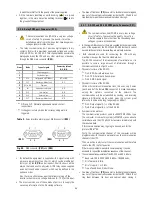
Connect the power supply cables R-N to the bypass terminals
(X14)
and
(X17), respecting the order of phase and neutral
indicated on the label of the equipment and in this manual. If the
order of the phase and neutral is not respected, the equipment
will be damaged seriously.
In case of discrepancies between the label and the instructions
of this manual, the label will always prevail.
5.2.3. Connection to the output, terminals (X6 to X9).
•
As this is an equipment with class I protection against
electrical shocks, it is essential to install the protection earth
conductor (connect earth ( ) ). Connect this conductor
to terminal
(X5)
, before supplying voltage to the input
terminals.
•
The «Recommended installation» information for each input
and output setting is available with the supplied
documentation, manual and/or CD. In that information is
shown the circuit dia- gram, as well as the protection size and
minimum cross section of the wires that are connected to
the equipment, taking into account the nominal operating
voltage. All figures are calculated for a
maximum total
cable length of 30 m
between the distribution panel
board, equipment and loads.
For longer lengths correct the cross sections accordingly, in
order to avoid dropping voltages, by respecting the Regulations
or norms corresponding to the country.
In the own documentation and for each setting, it is available
the information for «N» units in parallel.
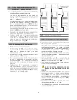
• Connect the output cables to the respective terminals
according to the available equipment setting.
For parallel systems, it will be needed to repeat the connections
that go from panel board to each equipment.
Connection to three phase output
:
Connect the loads to U-V-W-N output terminals
(X6)
,
(X7)
,
(X8)
and
(X9), respecting the phase rotation and neutral
indicated on the label of the equipment and in this manual. If the
phase rotation is not respected, the equipment will not operate.
In case of discrepancies between the label and the instructions
of this manual, the label will always prevail.
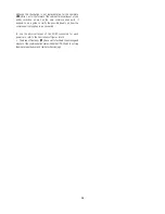
Connection to single phase output
:
Connect the loads to U-N output terminals
(X6)
and
(X9),
respecting the order of phase and neutral
indicated on
the label of the equipment and in this manual. If the order of the
phase and neutral is not respected, the equipment will be
damaged seriously.
In case of discrepancies between the label and the instructions
of this manual, the label will always prevail.
• With respect to the protection that must be placed on the
output of the switchgear or manual bypass panel board, we
recommend that the output power should be distributed in at
least four lines. Each one should have a circuit breaker
protection switch of the suitable value. This type of output
power distribution will allow, in the event of a breakdown in
any of the machines connected to the equipment that causes a
short circuit, will only affect to the line that is faulty. The rest of
the connected loads will have their continuity assured due to
the tripping of the protection of the line affected by the short
circuit only.
5.2.4. (X11, X12 and X23), with the battery modules (X47, X48
and X49).
•
As this is an equipment with class I protection against
electrical shocks, it is essential to install the protection earth
conductor (connect earth ( )). Connect this conductor
to terminal
(X5)
, before supplying voltage to the input
terminals.
• The original type of the battery circuit, preset from factory is
opened.
– +
Put the fuses
in the corresponding fuse holder switch and
turn
it «On»
when it is indicated only
, never before. To
operate in other way, can cause
irreversible damages to the
equipment or serious and/or very serious injuries
to the
fitter, as he has been exposed to a possible
electrical
discharge
during the connection of the UPS with the battery
set or battery cabinet.
•
Do manoeuvre the battery fuse holder switch and/or
switch, when the equipment is turned on. This
mechanisms
cannot be turned on/off with load
.
• The connection of the battery cabinet with a UPS with power
rate higher than 20 kVA (LV) / 40 kVA (HV) or for B1 models, will
be done with the supplied cable bundle, by connecting one side
to terminals
(X11)
,
(X23)
and
(X12)
of UPS and the other one
to terminals
(X47)
,
(X49)
and
(X48)
of battery module, always
respecting the stated polarity on the labelling of each element
and this manual, as well as the colour of the cables (red for
positive, black for negative, blue for middle tap (N) and green-
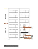
yellow for earth bonding), see Fig. 33.

