The
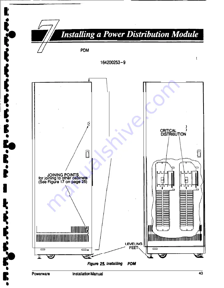
cabinet has two interface panels, each containing 42 poles
for breaker switches you can assign with flexibility to meet the needs of your
facility. Each panel is controlledby one 225 amp feeder breaker. The PDM cabinet
arrives as shown in Drawing
on page A-19 and Figure 25, below.
Before installing the PDM, be sure you have prepared the UPS according to the
instructions on page 19.
111111111111111111111111111111111111,.
JOINING POINTS
for joining to UPS
(See Figure 14
on page 23)
AC OUTPUT TO
LOAD
a
Cabinet
Plus so UPS
Summary of Contents for Plus 80
Page 1: ...0 Powerware Plus 80 Unintemqtibk Power Supply Operation 164200252 Rev A...
Page 55: ...a 1 a Pe WNP U N I N T E R R U P T I B L E P O W E R S Y S T E M S I i b I EXlDE ELECTRONICS...
Page 88: ...I I I I I I IO I I I I b I I NOTES 10 Powemam Plus 60 UPS ln stallation Manual...
Page 147: ...2 I FRONT Powerware Plus 80 UPS installation Manual A 13...
Page 153: ...5 61 CRE47Eo By L ORLANDO RMWON A ONE B 269r Powemare Plus 90 UPS lnstailation Manual A 19...


