OS-1933-E3-003
Scope of Manual
1-4
044-05243 Rev A
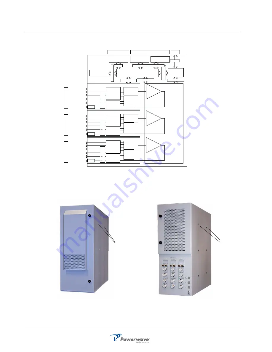
Figure 1-1 Outdoor System Block Diagram
PA0
Attenuator
Section
Controller
Ethernet
Interface
BTS TX1/RXm
BTS TX2/RXd
ANT. RXd
ANT. TX/RXm
Rectifier
Shelf
(x4)
PA Control I/O
RFCU Control I/O
Power and
Control Lines
DC Power
External Alarm
Inputs
Ext. Alarm Info.
Form-C
Interface
Form-C Data Out
VSWR
RFCU_Sector_0
PA1
Input
Filtering
Section
Output
Filtering
Section
Attenuator
Section
RFCU_Sector_1
PA2
Attenuator
Section
RFCU_Sector_2
SECTOR_0 RF
Interface
SECTOR_1 RF
Interface
SECTOR_2 RF
Interface
BTS TX3
BTS TX4
BTS TX1/RXm
BTS TX2/RXd
ANT. RXd
ANT. TX/RXm
VSWR
BTS TX3
BTS TX4
BTS TX1/RXm
BTS TX2/RXd
ANT. RXd
ANT. TX/RXm
VSWR
BTS TX3
BTS TX4
Input
Filtering
Section
Output
Filtering
Section
Input
Filtering
Section
Output
Filtering
Section
Bypass Switching
Bypass Switching
Bypass Switching
LNA
Section
LNA
Section
LNA
Section
Input Power, I/O_1,
and I/O_2
Fan Assy. (x2)
Fan Control
Internal User
Interface Panel
Rear Interface
Panel
Ethernet
AC Input
Figure 1-2 Outdoor System
Front
Rear
A
A
“
A
” locations my be used as lifting points.
Use minimum of two eyebolts.


