12
2-6. AMPLIFIER MODULE RS-232 CONNECTOR
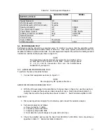
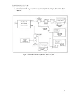
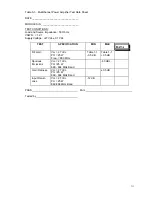
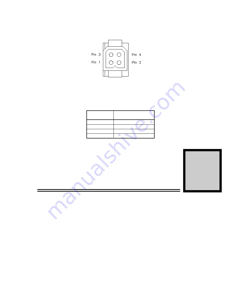
The RS-232 connection on the amplifier is made through a 4-pin male Molex connector (figure 2-2).
The connector is defined in table 2-2.
Figure 2-2. RS-232 Connector (on Rear of G3L-800-25-001 Module)
T
T
a
a
b
b
l
l
e
e
2
2
-
-
2
2
.
.
A
A
m
m
p
p
l
l
i
i
f
f
i
i
e
e
r
r
M
M
o
o
d
d
u
u
l
l
e
e
R
R
S
S
-
-
2
2
3
3
2
2
C
C
o
o
n
n
n
n
e
e
c
c
t
t
o
o
r
r
D
D
e
e
f
f
i
i
n
n
i
i
t
t
i
i
o
o
n
n
PIN
NUMBER
DESCRIPTION
1
RS-232 Rx
2
RS-232 Tx
3
Summary Alarm
4
Ground
OPERATING INSTRUCTIONS
3-1. INTRODUCTION
This section contains operating instructions for the Multicarrier Amplifier.
3-2. INITIAL START-UP AND OPERATING PROCEDURES
To perform the initial start-up, proceed as follows:
1.
Double check to ensure that all input and output cables are properly connected.
CAUTION
Before applying power, make sure that the input and output of the
amplifier are properly terminated at 50 ohms. Do not operate the
amplifier without a load attached. Refer to table 1-1 for input power
requirements. Excessive input power may damage the amplifier
NOTE
The output coaxial cable between the amplifier and the antenna must
be 50 ohm coaxial cable. Use of any other cable will distort the output.
Section
3


