13
2. Turn on supply that pr27 Vdc to the amplifier system.
3. Place power on/off switch on the amplifier front panel in the “on” (up) position.
4.
Turn on external exciter/transceiver and apply RF input signals.
PRINCIPLES OF OPERATION
4-1. INTRODUCTION
This section contains a functional description of the G3L-800-25-100 Multichannel
Power Amplifier.
4-2. RF INPUT SIGNAL
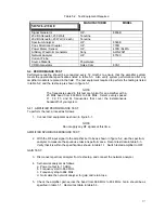
The maximum input power should not exceed the limits specified in table 1-1.
4-3. RF OUTPUT LOAD
The load impedance should be as good as possible (1.5:1 or better) in the working
band for good power transfer to the load.
4-4. AMPLIFIER FUNCTIONAL DESCRIPTION
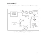
The G3L-800-25-001 amplifier (figures 1-1, 1-2, and 4-1) is a linear, multichannel
power amplifier that operates in the 25 MHz frequency band from 869 MHz to 894
MHz at an output power of 25 watts. Each amplifier is a self-contained module
and is functionally independent of any other amplifier modules in the system.
Each amplifier module has an alarm board that monitors the amplifier
performance. If a failure or fault occurs in an amplifier module, it is transmitted to
the host system via the D-subminiature 21Wa4 connector at the rear of the
module.
The amplifier is compliant to the requirements of FCC Part 22 and TIA/EIA IS97A
with respect to spurious emissions. Constant gain is maintained by continuously
comparing active paths with passive references, and correcting for small
variations through the RF feedback controls. All gain variations, for example
those due to temperature, are reduced to the passive reference variations. The
amplifier module is comprised of:
A preamp
A driver amplifier
A main amplifier
An error and preerror amplifier
Section
4


