3
TABLE OF CONTENTS (Continued)
Par.
Section 5
Page
No.
Maintenance
No.
5-1
Introduction .............................................................................................5-1
5-2
Periodic Maintenance..............................................................................5-1
5-3
Test Equipment Required For Test .........................................................5-1
5-4
Performance Test....................................................................................5-2
5-4.1 Amplifier Performance Test.....................................................................5-2
5-5
Field Replacement of the Module ...........................................................5-7
Section 6
Troubleshooting
6-1
Introduction .............................................................................................6-1
6-2
Troubleshooting ......................................................................................6-1
6-3
Return for Service Procedures ................................................................6-1
6-3.1 Obtaining an RMA ...................................................................................6-1
6-3.2 Repackaging for Shipment......................................................................6-1
LIST OF ILLUSTRATIONS
Figure
Page
No.
No.
1-1
G3L-800-25-001 Amplifier Showing Front Panel.....................................1-3
1-2
G3L-800-25-001 Amplifier Showing Rear Panel .....................................1-4
2-1
Power, Alarm, Control, and RF Connector (D-Subminiature 21WA4, Male
Connector) .........................................................................................................2-3
2-2
RS-232 Connector (on Rear of G3L-800-25-001 Module) ......................2-4
4-1
G3L-800-25-001 Multi Channel Power Amplifier Functional Block Diagram
4-2
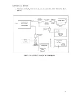
5-1
G3L-800-25-001 Amplifier Test Setup Diagram ......................................5-3
LIST OF TABLES
Table
Page
No.
No.
1-1
G3L-800-25-001 Multichannel Power Amplifier Functional Specifications1-2
2-1
Amplifier Module Power, Alarm, Control, and RF Connector Definition ..2-3
2-2
Amplifier Module RS-232 Connector Definition.......................................2-4
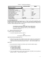
5-1
Periodic Maintenance..............................................................................5-1
5-2
Test Equipment Required .......................................................................5-2


