background image

P

OWERWINCH

24'


C

LASS 

R

OPE 

A

NCHOR 

W

INCH


W

IRING THE 

U

NIT


WARNING


A

LWAYS

  disconnect  the  battery  before  working  on 

electrical equipment. 

WARNING


A

LWAYS 

use the recommended wire size and rated circuit 

breakers.  Failure to use the furnished and recommended sizes can cause a fire 

hazard and void warranty. 

NOTICE  

When routing the wiring, avoid sources of heat. 

NOTICE  

When routing the wiring, avoid sharp edges that can cut or fray 

the wire insulation. 

1. Determine  the  switch  location.  

Ensure  that  there  is  adequate  room 

behind the mounting surface for the 

switch and wiring. 

2. Drill  a  1/2"  hole  through  the

mounting surface. 

3. Center  the  label  over  the  hole,

remove  the  release  paper  and

attach. 

4.

Route one R

ED  

and one B

LACK 

12 awg wire from the anchor to the switch


location.  Be sure to allow adequate wiring to make connections, allow the


wire to have some slack when routing.  Secure the wires with wire ties.

5.

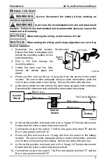
At the winch, attach the new wires to the motor wires using the butt connectors.


Ensure that the crimps are solid and that the wires cannot come loose

Anchor

Winch

Control

Switch

(D)

(C)

(B)

(A)

15A Circuit Breaker

Battery

Black 

12awg

Red 

12awg

Black 

12awg

Red 

12awg

PW24003

6. At the switch position, terminate wire with a 12awg 1/4" female disconnect.

Ensure that the crimp is solid and cannot pull off.

7. Connect the wires to the switch.  The R

ED

 wire goes to terminal "B" and the

B

LACK

 wire goes to terminal "A".

8. Route one R

ED 

and one B

LACK 

12 awg wire from the switch to the battery

location.  Be sure to allow adequate wiring to make connections, allow the

wire to have some slack when routing.  Secure the wires with wire ties.

9. At the switch position, terminate wire with a 12awg 1/4" female disconnect.

Ensure that the crimp is solid and cannot pull off.

10. Connect the wires to the switch.  The R

ED

 wire goes to terminal "C" and the

B

LACK

 wire goes to terminal "D".

ANCHOR WINCH

CONTROL SW

ITCH

DOWN

POWERWINCH

Switch

Switch

Boot

PW24002a

1/2" Hole

Switch Label

Summary of Contents for PW24101

Page 1: ...hroom or navy type anchors using nylon rope These anchor winches feature power in and power out operation with a switch that can be mounted on the helm The 24 anchor winch has an integral roller davit...

Page 2: ...ns may differ from the information given SFEG reserves the right to cancel change alter or add any parts and assemblies described in this manual without prior notice SFEG agrees to allow the reproduct...

Page 3: ...nd between the load and the winch Serious injury could occur if the rope breaks WARNING NEVER wear loose fitting clothes scarves ties or jewelry when operating the winch Loose clothing can become caug...

Page 4: ...L x W x D 40 lbs max 80 ft sec 3 16 x 100 Nylon 12VDC 15A 20 lbs 10 5 x 6 x 9 25 REQUIRED MATERIALS NOT INCLUDED WITH WINCH Marine grade plywood for under deck support optional Loctite 242 thread loc...

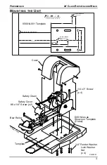
Page 5: ...Fender Washer Lock Washer Nut x 4 Template Drill Holes as Shown on Template 5 total Edge of Deck Align End of Frame with Deck Edge Center of Roller Mounting Template For 24 Anchor Winch For Technical...

Page 6: ...ach the safety bar to the other end of the chain using a split ring NOTE It may be necessary to remove links after the anchor has been attached and drawn up The chain should be tight when attached to...

Page 7: ...re the wires with wire ties 5 At the winch attach the new wires to the motor wires using the butt connectors Ensure that the crimps are solid and that the wires cannot come loose Anchor Winch Control...

Page 8: ...toward anchor winch Make sure rope is not twisted or kinked and can freely run through bow roller or davit 2 Insert the rope through the hole located in the side of the drum from the side opposite of...

Page 9: ...outing flush exterior of winch with fresh water Use only mild detergents to clean exterior Use of solvents can cause damage to the finishes and seals as well as void product warranty Check electrical...

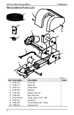
Page 10: ...4501 1 2 3 4 5 6 7 8 9 10 10 10 Item Description Description Notes 1 R001418 Cover Kit 2 R001417 Motor Kit 3 R001421 Rope Spool 4 R001425 Bearing 5 R001423 Safety Chain Kit 6 R001426 Bow Roller Kit 7...

Page 11: ...ct that is not specifically approved by SFEG g Any incidental indirect or consequential loss damage or expense that may result from any defect failure or malfunction of the product h The removal or al...

Page 12: ...WERWINCH 10 FOR YOUR RECORDS DEALER INSTALLER NAME ADDRESS PHONE PURCHASE DATE PART NUMBER SERIAL NUMBER PRODUCT NAME OR DESCRIPTION Retain your original proof of purchase It is requiRED for all warra...

Reviews: