background image

36',


41'

 AND 

46'


A

NCHOR 

W

INCH

P

OWERWINCH


36'


&


41'


W

IRING


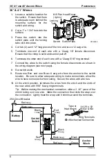
1.

Locate a suitable location for
the switch.  Ensure that there 
is adequate room behind the 
mounting surface for the 
switch and wiring. 

2.

Cut a 1" x 1 3/4" hole into the
surface.

3.

Press the switch into the
switch plate until the locking
tabs click into place.

4.

Cut two (2) each 12" long pieces of the 

RED  

and 

BLACK 

12 awg wire.

5.

Terminate one end of each wire with a 12awg 1/4" female disconnect.
Ensure that the crimp is solid and cannot pull off.

6.

Terminate the other end of each wire with a 12awg 5/16" ring terminal.

7.

Connect the wires to the switch using the female disconnects as shown in
the wiring diagram (see next page).

8.

Set switch aside.

9.

Route one R

ED  

and one B

LACK 

6 awg wire from the anchor to the switch

location.  Be sure to allow adequate wiring to make connections, allow the
wire to have some slack when routing.  Secure the wires with wire ties.

10. At the winch position, terminate the wires from the winch and the ends of

the new wires with 5/16" 6 awg ring terminals.

Tip:  Before making the mechanical connection, slide a 2 1/2" piece of the
shrink tubing over one wire.  Make the connection then slide the wrap over
the connection.  Lightly heat the wrap until it shrinks around the terminals.

Anchor

Winch

Green

Black

Red 

6awg

Black 

6awg

Control

Switch

Black 

6awg

PW46004

Ring Terminals

1/4-20 x 1/2
Screw & Nut

Tape or

Heat Shrink

= Mechanical Connection

Red

12awg

Black

12awg

Red 

6awg

25A Circuit Breaker

Battery

Black

12awg

Red

12awg

(A)

(B)

(C)

(D)

Powerwinch

Windlass

To release anchor hold

switch down for 5 seconds

1"

1 3/4"

#10 Pan Head Screw
(4 plcs)

PW46005

Switch Switch Plate

Locking

Tabs

Summary of Contents for PW46101

Page 1: ...e to a specific model are labeled appropriately FREE FALL ROPE AND CHAIN ANCHOR WINCH PW46101 12 Volt Powered Winch Power In Freewheel out operation Thoroughly read the manual furnished with this prod...

Page 2: ...ed in this manual without prior notice SFEG agrees to allow the reproduction of this document for use with SFEG products only Any other reproduction or translation of this document in whole or part is...

Page 3: ...the winch for overhead lifting CAUTION NEVER attempt to pull a load greater than the rated load of the winch CAUTION ALWAYS stand away from the winch during operation ALWAYS keep objects people and an...

Page 4: ...10 x 3 4 Screw 1 Switch DPDT 1 Switch DPDT 1 Switch SPDT 1 Relay Module 4 6awg to 8awg splices 2 6 Red Jumper 8awg 2 6 Black Jumper 8awg 1 Mounting Template 1 Mounting Template 1 Mounting Template RE...

Page 5: ...chain rodes a rode is a length of rope and chain It is very important that only sizes and brands of spliced rope and chain rodes specified below are used Use of non specified ropes and chains could c...

Page 6: ...er Lock Washer 5 16 Nut x3 Rope Locker PW46006 Drill Holes as Shown on Template 5 total BOW OF BOAT Center Of Rope Anchor Winch To Davit 5 16 7 9mm 2 5 16 58 7mm 5 1 2 139 7mm 6 7 8 174 6mm 3 1 4 82 6...

Page 7: ...inch Hand tighten until snug 6 Align the winch over the rode glide and align the studs with the holes in the deck Insert the wires through the hole in the deck Lower the winch to the deck 7 Under the...

Page 8: ...CK 6 awg wire from the anchor to the switch location Be sure to allow adequate wiring to make connections allow the wire to have some slack when routing Secure the wires with wire ties 10 At the winch...

Page 9: ...D and 1 BLACK 6 awg wire from the battery to the switch location Be sure to allow adequate wiring to make connections allow the wire to have some slack when routing Secure the wires with wire ties 17...

Page 10: ...on Be sure to allow adequate wiring to make connections allow the wire to have some slack when routing Secure the wires with wire ties 6 At the switch terminate the ends of the wires with 1 4 16 awg i...

Page 11: ...jumper ends with 8awg 3 8 insulated female disconnects c Attach the battery wires to the relay terminals red and black 17 At the battery terminate the wires with 5 16 6 awg ring terminals Attach the B...

Page 12: ...ing the switch in the up position 4 Tie the rope off to a deck cleat DO NOT use the winch to tie off the anchor 5 Place the boat s motors in neutral and allow the boat to drift back and set the anchor...

Page 13: ...2 Confirm connections are tight clean 3 Check wires if worn or bare that may cause shorts Correct as required B Check circuit breaker at battery Bypass circuit breaker and test winch Does the winch r...

Page 14: ...ncho r hold switch down for 5 secon ds Powerwinch Windlass To releas e ancho r hold switch down for 5 secon ds Windlass 46 DETAIL A Windlass 36 41 Windlass 36 41 DETAIL A Windlass 46 A 1 4 2 2 5 4 6 7...

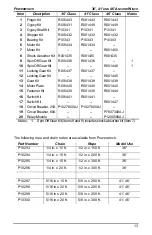
Page 15: ...Plate R001440 R001440 R001440 15 Fastener Kit R001439 R001439 R001444 16 Switch Kit R001441 R001441 17 Switch Kit R001447 18 Circuit Breaker 25A P1027600AJ P1027600AJ 19 Circuit Breaker 60A P7837300A...

Page 16: ...ct that is not specifically approved by SFEG g Any incidental indirect or consequential loss damage or expense that may result from any defect failure or malfunction of the product h The removal or al...

Reviews: