P
OWERWINCH
36',
41'
AND
46'
A
NCHOR
W
INCH
7
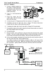
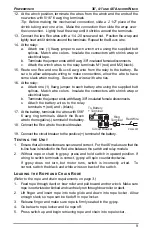
11. Connect the motor G
REEN
wire to the new R
ED
wire with a 1/4 -20 screw and nut.
Position the wrap and lightly heat until it shrinks around the terminals.
12. Connect the motor B
LACK
wire to the new B
LACK
wire with a 1/4 -20 screw and
nut. Position the wrap and lightly heat until it shrinks around the terminals.
13. At the switch position, terminate the ends of the new wires with 5/16" 6 awg
ring terminals.
14. Connect the switch R
ED
wire to the winch R
ED
wire with a 1/4 -20 screw and nut.
Position the wrap and lightly heat until it shrinks around the terminals.
15. Connect the switch B
LACK
wire to the winch B
LACK
wire with a 1/4 -20 screw and
nut. Position the wrap and lightly heat until it shrinks around the terminals.
16. Route 1 R
ED
and 1 B
LACK
6 awg wire from the battery to the switch location.
Be sure to allow adequate wiring to make connections, allow the wire to
have some slack when routing. Secure the wires with wire ties.
17. At the switch position, terminate the ends of the new wires with 5/16" 6 awg
ring terminals.
18. Connect the switch R
ED
wire to the battery R
ED
wire with a 1/4 -20 screw and nut.
Position the wrap and lightly heat until it shrinks around the terminals.
19. Connect the switch B
LACK
wire to the battery B
LACK
wire with a 1/4 -20 screw and
nut. Position the wrap and lightly heat until it shrinks around the terminals.
20. Push the switch and wires into the switch mounting hole. Secure the switch plate
using 4 #10 screws.
21. At the battery location, terminate each wire with a 5/16" ring terminal.
22. Attach the B
LACK
wire to the negative (-) post of the battery.
23. Attach the R
ED
wire to the post on the circuit breaker.
24. Attach the circuit breaker to the positive (+) post of the battery.


